
Data Sheet

PCA9685 All information provided in this document is subject to legal disclaimers. © NXP B.V. 2010. All rights reserved.
Product data sheet Rev. 3 — 2 September 2010 47 of 51
NXP Semiconductors
PCA9685
16-channel, 12-bit PWM Fm+ I
2
C-bus LED controller
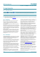
For further information on temperature profiles, refer to Application Note AN10365
“Surface mount reflow soldering description”.
18. Abbreviations
MSL: Moisture Sensitivity Level
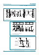
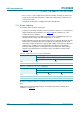
Fig 38. Temperature profiles for large and small components
001aac84
4
temperature
time
minimum peak temperature
= minimum soldering temperature
maximum peak temperature
= MSL limit, damage level
peak
temperature
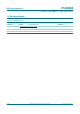
Table 18. Abbreviations
Acronym Description
CDM Charged-Device Model
DUT Device Under Test
EMI ElectroMagnetic Interference
ESD ElectroStatic Discharge
HBM Human Body Model
I
2
C-bus Inter-Integrated Circuit bus
LCD Liquid Crystal Display
LED Light Emitting Diode
LSB Least Significant Bit
MM Machine Model
MSB Most Significant Bit
NMOS Negative-channel Metal-Oxide Semiconductor
PCB Printed-Circuit Board
PMOS Positive-channel Metal-Oxide Semiconductor
POR Power-On Reset
PWM Pulse Width Modulation; Pulse Width Modulator
RGB Red/Green/Blue
RGBA Red/Green/Blue/Amber
SMBus System Management Bus