
Data Sheet


PCA9685 All information provided in this document is subject to legal disclaimers. © NXP B.V. 2010. All rights reserved.
Product data sheet Rev. 3 — 2 September 2010 42 of 51
NXP Semiconductors
PCA9685
16-channel, 12-bit PWM Fm+ I
2
C-bus LED controller
14. Test information
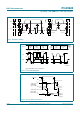
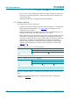
R
L
= Load resistor for LEDn.
C
L
= Load capacitance includes jig and probe capacitance.
R
T
= Termination resistance should be equal to the output impedance Z
o
of the pulse generators.
Fig 34. Test circuitry for switching times
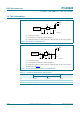
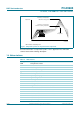
R
L
= Load resistor for LEDn.
C
L
= Load capacitance includes jig and probe capacitance.
R
T
= Termination resistance should be equal to the output impedance Z
o
of the pulse generators.
Test data are given in Tab le 15
.
Fig 35. Test circuitry for switching times for enable/disable
Table 15. Test data for enable/disable switching times
Test Load Switch
C
L
R
L
t
PD
50 pF 500 Ω open
t
PLZ
, t
PZL
50 pF 500 Ω V
DD
× 2
t
PHZ
, t
PZH
50 pF 500 Ω V
SS
PULSE
GENERATOR
V
O
C
L
50 pF
R
L
500 Ω
002aab880
R
T
V
I
V
DD
DUT
V
DD
open
V
SS
PULSE
GENERATOR
V
O
C
L
50 pF
R
L
500 Ω
002aad81
1
R
T
V
I
V
DD
DUT
R
L
500 Ω
V
DD
× 2
open
V
SS
S1