
Data Sheet

PCA9685 All information provided in this document is subject to legal disclaimers. © NXP B.V. 2010. All rights reserved.
Product data sheet Rev. 3 — 2 September 2010 41 of 51
NXP Semiconductors
PCA9685
16-channel, 12-bit PWM Fm+ I
2
C-bus LED controller
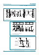
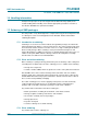
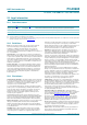
Fig 31. Definition of timing
t
SP
t
BUF
t
HD;STA
PP S
t
LOW
t
r
t
HD;DAT
t
f
t
HIGH
t
SU;DAT
t
SU;STA
Sr
t
HD;STA
t
SU;STO
SDA
SCL
002aaa986
Rise and fall times refer to V
IL
and V
IH
.
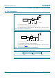
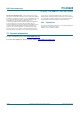
Fig 32. I
2
C-bus timing diagram
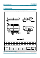
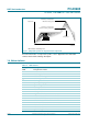
Fig 33. t
PLZ
, t
PZL
and t
PHZ
, t
PZH
times
SCL
SDA
t
HD;STA
t
SU;DAT
t
HD;DAT
t
f
t
BUF
t
SU;STA
t
LOW
t
HIGH
t
VD;ACK
002aab285
t
SU;STO
protocol
START
condition
(S)
bit 7
MSB
(A7)
bit 6
(A6)
bit 1
(D1)
bit 0
(D0)
1
/ f
SCL
t
r
t
VD;DAT
acknowledge
(A)
STOP
condition
(P)
002aad81
0
t
PLZ
t
PHZ
outputs
disabled
outputs
enabled
outputs
enabled
LEDn output
LOW-to-OFF
OFF-to-LOW
LEDn output
HIGH-to-OFF
OFF-to-HIGH
OE input
V
I
V
OL
V
OH
V
DD
V
M
V
M
V
X
V
Y
V
M
V
SS
t
PZL
t
PZH
V
M
V
SS