
Data Sheet

PCA9685 All information provided in this document is subject to legal disclaimers. © NXP B.V. 2010. All rights reserved.
Product data sheet Rev. 3 — 2 September 2010 4 of 51
NXP Semiconductors
PCA9685
16-channel, 12-bit PWM Fm+ I
2
C-bus LED controller
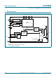
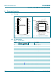
5. Block diagram
Remark: Only one LED output shown for clarity.
Fig 1. Block diagram of PCA9685
A0 A1 A2 A3 A4 A5
002aac824
I
2
C-BUS
CONTROL
INPUT FILTER
PCA9685
POWER-ON
RESET
SCL
SDA
V
DD
V
SS
LED
S TAT E
SELECT
REGISTER
PWM
REGISTER X
BRIGHTNESS
CONTROL
MUX/
CONTROL
OE
'0' – permanently OFF
'1' – permanently ON
V
DD
LEDn
PRESCALE
25 MHz
OSCILLATOR
CLOCK
SWITCH
EXTCLK