
Data Sheet

PCA9685 All information provided in this document is subject to legal disclaimers. © NXP B.V. 2010. All rights reserved.
Product data sheet Rev. 3 — 2 September 2010 36 of 51
NXP Semiconductors
PCA9685
16-channel, 12-bit PWM Fm+ I
2
C-bus LED controller
I
2
C-bus address = 1010 101x.
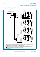
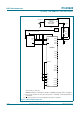
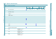
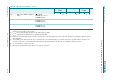
Remark: Set INVRT = 0, OUTDRV = 1, OUTNE = 01 (MODE2 register bits) for this configuration.
(1) Resistor value should be chosen by referencing Section 7 of UM10204, “I
2
C-bus specification and
user manual”.
(2) OE
requires pull-up resistor if control signal from the master is open-drain.
Fig 27. LCD backlighting application
PCA9685
LED0
LED1
SDA
SCL
OE
V
DD
= 2.5 V, 3.3 V or 5.0 V
ASIC/MICRO
002aac828
SDA
SCL
(1)
OE
(1)
LED2
LED3
A0
A1
A2
V
DD
A3
A4
A5
V
SS
10 kΩ
(2)
LED4
LED5
LED6
LED7
LED8
LED9
LED10
LED11
LED12
LED13
LED14
LED15
CONSTANT
CURRENT
SWITCH MODE
REGULATOR
FB
OUT
V
IN
I
constant
LIGHT
SENSOR
LED supply
R
sense
LED
string
EXTCLK