
Data Sheet

PCA9685 All information provided in this document is subject to legal disclaimers. © NXP B.V. 2010. All rights reserved.
Product data sheet Rev. 3 — 2 September 2010 28 of 51
NXP Semiconductors
PCA9685
16-channel, 12-bit PWM Fm+ I
2
C-bus LED controller
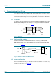
7.7 Using the PCA9685 with and without external drivers
The PCA9685 LED output drivers are 5.5 V only tolerant and can sink up to 25 mA at 5 V.
If the device needs to drive LEDs to a higher voltage and/or higher current, use of an
external driver is required.
• INVRT bit (MODE2 register) can be used to keep the LED PWM control firmware the
same independently of the type of external driver. This bit allows LED output polarity
inversion/non-inversion only when OE
=0.
• OUTDRV bit (MODE2 register) allows minimizing the amount of external components
required to control the external driver (N-type or P-type device).
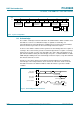
[1] When OE = 1, LED output state is controlled only by OUTNE[1:0] bits (MODE2 register).
[2] Correct configuration when LEDs directly connected to the LEDn outputs (connection to V
DD
through current limiting resistor).
[3] Optimum configuration when external N-type (NPN, NMOS) driver used.
[4] Optimum configuration when external P-type (PNP, PMOS) driver used.
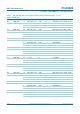
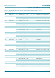
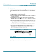
Table 11. Use of INVRT and OUTDRV based on connection to the LEDn outputs when OE =0
[1]
INVRT OUTDRV Direct connection to LEDn External N-type driver External P-type driver
Firmware External
pull-up
resistor
Firmware External
pull-up
resistor
Firmware External
pull-up
resistor
0 0 formulas and LED
output state values
inverted
LED current
limiting R
[2]
formulas and LED
output state
values inverted
required formulas and LED
output state values
apply
required
0 1 formulas and LED
output state values
inverted
LED current
limiting R
[2]
formulas and LED
output state
values apply
[3]
not
required
[3]
formulas and LED
output state values
inverted
not required
1 0 formulas and LED
output state values
apply
[2]
LED current
limiting R
formulas and LED
output state
values apply
required formulas and LED
output state values
inverted
required
1 1 formulas and LED
output state values
apply
[2]
LED current
limiting R
formulas and LED
output state
values inverted
not required formulas and LED
output state values
apply
[4]
not
required
[4]
INVRT = 0
OUTDRV = 1
INVRT = 1
OUTDRV = 1
INVRT = 1
OUTDRV = 0
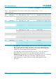
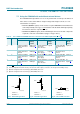
Fig 13. External N-type driver Fig 14. External P-type driver Fig 15. Direct LED connection
LED0
+5 V
002aad16
9
LED0
+5 V
002aad17
0
LED0 +V
DD
002aad17
1