General Information How to Use This Standard Part Catalog.................................................................................................................................................................................................................... 2 Index by Part Number............................................................................................................................................................................................................................
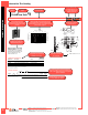
How to Use This Catalog Base part number Semiconductor device Icons indicate that a mounting kit, grease or epoxy can be used with the heat sink Style description for heat sink TO-220 Heat Sinks Grease & Epoxy page112 Channel style heat sink with folded back fins Semiconductor devices have been included in photos to assist in determining mounting position. Thermal graphs show natural and forced convection based on black anodize finish.
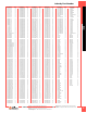
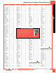
Part Number Page 10-5597-02G 14 10-5597-22G 14 10-5597-33G 14 10-5607-04G 14 10-5607-05G 14 10-5634-01G 12 10-6326-27G 14 10-6326-28G 14 10-6327-01G 14 10-BRD1-01G 12 10-BRD1-03G 12 10-BRD1-04G 12 10-BRD1-05G 12 10-BRD1-07G 12 10-BRD2-01G 12 10-CLS1-01G 12 10-CLS2-01G 12 10-L4LB-03G 14 10-L4LB-05G 14 10-L4LB-11G 14 10-THMA-01G 12 10-TNT2-01G 14 2317B-EP11-BGS1G 18 2319B-TACHG 17 2321B-TACHG 17 2327B-CP50G 16 2327B-TACHG 16 2332B-TACHG 17 2338B-TACHG 17 2342B-TACHG 17 2518B-EP11-BGS2G 18 2519B-EP11-BGS5G 18
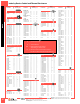
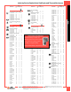
Index by Device Cooled and Thermal Resistance Part Number θn Board Mounting Page AXIAL LEAD 6000UG 6000DG 15.0 15.0 V V 77 77 BRIDGE RECTIFIERS INDEX 6222BG 6223BG 6224BG 9.4 9.4 9.4 V V V 77 77 77 DIPS 501200B00000G 501100B00000G 501000J00000G 501000B00000G 580300B00000G 580400B00000G 508500B00000G 508600B00000G 580100B00000G 580100W00000G 508700B00000G 6284BG 560200B00000G 560200W00000G 580200B00000G 580200W00000G 580500B00000G 580600B00000G Part Number D2PAK TO-263 573300D00010G 16.
Index by Device Cooled and Thermal Resistance 591202B04000G 591302B00000G 591302B02800G 591302B04000G 579802B00000G 579802B03300G 579902B00000G 579902B03300G 577102B00000G 577102B04000G 7173DG 6236BG 6236PBG 6237BG 6237PBG 577202B00000G 577202B04000G 507302B00000G 507302J00000G 542502B00000G 542502D00000G TV96G PF752G 576014B00000G 574402B00000G 574402B03200G 574102B00000G 574102B03300G 6043PBG 592502B03400G 592502U03400G 574602B00000G 574602B03300G 574502B00000G 574502B03300G 6110PBG 576012B00000G 7137DG
Index by Device Cooled, Heat Sink Style, and Thermal Resistance Part Number θn Board Mounting Page θn Part Number AXIAL LEAD Board Mounting Page Part Number SMT 15.0 V 77 D-Pak TO-252 6000DG 15.0 V 77 573100D00010G 573100D00000G Extruded Collar Heat Sinks 15.0 15.0 H H 24 24 18.0 18.0 H H 24 24 7109D/TRG 11.0 H 7109DG 11.0 H D2 Pak TO-263 SO10 (MO-184) 25 25 15.0 15.0 H H 24 24 23 7106D/TRG 7106DG D3 Pak TO-268 23 23 573400D00010G 573400D00000G 14.0 14.
Index by Device Cooled, Heat Sink Style, and Thermal Resistance θn Board Mounting Page Part Number θn Board Mounting Page Hat Section Heat Sinks TO-202 CONTINUED TV96G TV97G Low Cost Slide On Cooler Heat Sinks 24.0 20.0 Part Number θn Board Mounting Page 534202B02853G 13.4 V 38 H H–V 53 53 534202B03453G 577922B00000G 13.4 13.2 V V 38 41 579604B00000G 579604B03300G 24.0 24.0 V V 63 63 High Rise Style Heat Sinks 530101B00100G 6.3 V 54 578622B03200G 563002B00000G 13.2 13.
Index by Device Cooled, Heat Sink Style, and Thermal Resistance Part Number θn Board Mounting Page INDEX TO-220 CONTINUED SW38-2G 10.2 V 56 SW38-4G SW38-6G 10.2 10.0 V V 56 59 534002B02554G 533202B02551G 9.0 9.0 V V 50 55 513202B02500G SW50-2G 9.0 8.8 V V 58 56 SW50-4G YB32-4G 8.8 8.4 V V 56 61 533302B02551G 8.0 V 55 530002B02500G 513302B02500G 2.6 8.0 V V 56 58 531302B02500G 531302V02500G 8.0 8.0 V V 59 59 531202V02500G 531202B02500G 7.5 7.5 V V 59 59 BW38-2G 7.
How To Select a Heat Sink How to select a heat sink The basic equation for heat transfer or power dissipation may be stated as follows: HOW TO SELECT A HEAT SINK ΔT PD = ΣRθ Where: PD = the power dissipated by the semiconductor device in watts. ΔT = the temperature difference of driving potential which causes the flow of heat. ΣRθ = the sum of the thermal resistances of the heat flow path across which ΔT exists.
Example A Example B Find a space saving heat sink to keep a TO-220 device below the maximum 150°C junction temperature in natural convection. Device will be screw mounted with an electrically conductive interface. Find a heat sink to keep a TO-220 device below the maximum 150 °C junction temperature in forced convection at 400 ft/min. Device must be electrically insulated and mounted with a labor saving clip.
200 Air Velocity—Feet Per Minute 400 600 800 1000 20 80 16 60 12 40 8 20 4 0 0 0 1 2 3 4 Heat Dissipated—Watts EXAMPLE: The output air volume of a fan is given as 80 CFM. The output area is 6 inches by 6 inches or 36 in2 or 25 ft2.
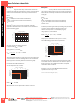
BGA–Solder Anchor HEAT SINKS FOR IC PACKAGES Solder anchor attachment Aavid's unique Solder anchor attachment method uses two or four small Solder anchors attached to the circuit card and a wire spring clip to securely fasten the heat sink to the device. This method is rugged, compact and allows for easy removal in case of rework. All products include a phase change pad suitable for most IC package styles to optimize thermal performance.
BGA–Solder Anchor Solder anchor heat sinks mechanical drawings FIGURE 1 FIGURE 2 12.70 (0.500) "W" "L" 54.74 (2.155) "W" 12.70 (0.500) "A" "L" "H" FIGURE 3 HEAT SINKS FOR IC PACKAGES "H" 15.00 (0.591) 45.88 "W" (1.806) 15.00 (0.591) "H" "L" Board mounting pattern information for solder anchor heat sinks FIGURE A FIGURE B 48.26 (1.900) 35.56 (1.400) ø 0.97 ± 0.03 (0.038 ± 0.001) PLATED THROUGH HOLES 4 X Ø 0.97 0.03 (0.038 0.001) PLATED THROUGH HOLES 4X 26.67 (1.050) 53.34 (2.100) 66.
BGA–Push Pin Attachment HEAT SINKS FOR IC PACKAGES Push pin attachment Push pin heat sinks require two 3.10mm holes in the circuit card to quickly attach the heat sink over the device. The one piece design makes assembly a snap. Pressure is maintained by the tension of the push pin coil springs to ensure even pressure across the device. Push pins provide a greater margin of reliability in applications where gravity or vibration may cause tapes or adhesives to fail.
BGA–Push Pin Attachment Mechanical drawings FIGURE 2 FIGURE 3 "T" "T" 46.60 (1.835) "H" 41.70 (1.642) "H" "S" 41.50 (1.634) "L" "L" "L" "W" "W" "T" "H" "W" FIGURE 5 FIGURE 4 "T" "S" "H" HEAT SINKS FOR IC PACKAGES FIGURE 1 "S" "L" 20.02 "L" (0.788) "T" "W" 10.69 (0.421) "H" "W" Board mounting pattern information FIGURE A FIGURE B ø 3.10 ± 0.030 (0.122 ± 0.001) THROUGH HOLES (UNPLATED) 2X 46.60 (1.830) REF 32.95 (1.297) 59.00 (2.320)REF Ø 3.10 0.03 (0.122 0.
BGA–Tape Attachment HEAT SINKS FOR IC PACKAGES Heat sinks for plastic BGA packages "H" "L" "W" Pressure sensitive, thermally conductive adhesive tape easily and reliably bonds a heat sink to an integrated circuit package. Tapes provide high thermal conductivity and exceptional bonding properties. Adhesives are formulated for plastic and metal/ceramic packages.
BGA–Tape Attachment "H" "L" "W" HEAT SINKS FOR IC PACKAGES Heat sinks for metal/ceramic BGA packages Material: Aluminum ORDERING INFORMATION Part Number “W” (mm) “L” (mm) “H” (mm) θn 2 θf 3 Finish Tape Code1 10 x 10 Metal / Ceramic 375224B00032G 10.20 11.10 10.20 71.40 21.20 Black anodize 32 23 x 23 Metal / Ceramic 374024B00032G 23.00 23.00 10.00 40.00 11.69 Black anodize 32 23 x 23 Metal / Ceramic 374124B00032G 23.00 23.00 18.00 23.40 7.
BGA–Clip Attachment HEAT SINKS FOR IC PACKAGES Clip attachment "H" "L" Aavid's BGS Clip heat sinks provide a mechanical attachment alternative to tape applications where it is desirable to attach the heat sink directly to the device. The unique clip uses spring pressure to ensure even contact across the device while the end plates firmly engage the edge of the package, locking the heat sink in place. Each heat sink uses pre-applied thermal grease for optimum thermal performance.
BGA – Bi Directional "W" "L" "H" Designed for applications with airflow traveling in a single direction, these heat sinks are suitable for a variety of standard square IC packages. Models are available with pre-applied thermal tape for easy attachment to the IC. Epoxy attach models are also available.
DIPS 0 200 Air Velocity—Feet Per Minute 400 600 800 1000 20 Mounting Surface Temp Rise Above Ambient—°C 100 Slide on heat sink with staggered fins attaches to 8 pin DIP packages quickly and easily. The heat sink features double spring action and locking catch to firmly attach the device creating a thermal conduction path on both the top and bottom surfaces. Available in two finishes. 80 16 60 12 40 8 20 4 0 0 0 0.4 0.8 1.2 1.
Slide on heat sink with staggered fins 0 200 Air Velocity—Feet Per Minute 400 600 800 Mounting Surface Temp Rise Above Ambient—°C 100 1000 10 80 8 60 6 40 4 20 2 0 0 Slide on heat sink with staggered fins attaches to 28 pin DIP packages quickly and easily. The heat sink features double spring action and locking catch to firmly attach the device creating a thermal conduction path on both the top and bottom surfaces. 0 0.4 0.8 1.2 1.
DIPS Slide on heat sink with staggered fins Air Velocity—Feet Per Minute 400 200 600 800 100 1000 20 80 16 60 12 40 8 20 4 0 0 Slide on heat sink with staggered fins attaches to 20 pin DIP packages quickly and easily. The heat sink features double spring action and locking catch to firmly attach the device creating a thermal conduction path on both the top and bottom surfaces. 0 0.4 0.8 1.2 1.6 Heat Dissipated—Watts 28.58 (1.
Grease & Epoxy page112 Extruded epoxy attach on heat sink with straight fins 0 200 Air Velocity—Feet Per Minute 400 600 800 Mounting Surface Temp Rise Above Ambient—°C 100 Extruded epoxy attach on heat sink with straight fins attaches to 24, 28, and 40 pin DIP packages quickly and easily. May be added before or after final board assembly. No additional board space is required.
SMT Surface mount heat sink for D-PAK (TO-252) package semiconductors 80 20 60 15 40 10 Case Temp Rise Rise Above Ambient—°C 20 5 0 0 0.0 0.5 1.0 1.5 2.0 Heat Dissipated—Watts 8.00 (0.315) Thermal Resistance From MTG Surface to Ambient—°C/Watt 1000 25 0 Surface mount heat sink for D-PAK (TO-252) package semiconductors remove the heat indirectly without contacting the device like traditional through hole heat sinks.
Surface mount heat sink for D 2 PAK (TO-263) package semiconductors Air Velocity—Feet Per Minute 400 200 600 800 0 1000 Mounting Surface Temp Rise Above Ambient—°C 100 Surface mount heat sink for D2 PAK (TO-263) package semiconductors remove the heat indirectly without contacting the device like traditional through hole heat sinks. The device and the heat sink are soldered directly to a modified drain pad creating a thermal transfer path from package tab to the heat sink.
THRU HOLE DISCRETE SEMICONDUCTOR PACKAGES SMT Footprints FIGURE A FIGURE B Recommended copper heat speader drain pad footprint Recommended heat sink solder mask opening W1 W W2 Note: The thickness of the drain pad is variable depending on the amount of heat generated by the SMT device, design limitations and process. L L 1.40 (0.060) 0.80 (0.030) “L” “W” “L” “W1” “W2” 573100 9.53 (0.375) 13.97 (0.550) 573100 9.02 (0.355) 13.46 (0.530) 8.89 (0.350) 573300 14.22 (0.560) 16.26 (0.
Grease & Epoxy page112 Channel style heat sink with folded back fins 0 200 Air Velocity—Feet Per Minute 400 600 800 Channel style heat sink with folded back fins for increased cooling surface area. Available with tin plated solderable tabs for easy attachment to the printed circuit card. Mounting Surface Temp Rise Above Ambient—°C 100 5 80 4 60 3 40 2 20 1 0 0 0 4 6 Heat Dissipated—Watts 8 5.08 14.48 (0.200) (0.570) 28.70 23.62 (1.130) (0.930) 2.02 (0.080) 10 3.18 (0.125) 4.45 (0.
TO-220 Heat Sinks Grease & Epoxy page112 Channel style heat sink with folded back fins Air Velocity—Feet Per Minute 400 200 600 800 44.45 (1.750) 100 5 80 4 60 3 40 2 20 1 0 0 0 Channel style heat sink with folded back fins for increased cooling surface area. Available with tin plated solderable tabs for easy attachment to the printed circuit card. 2 4 6 8 Heat Dissipated—Watts 7.87 (0.310) "X" 36.83 (1.450) 4.83 (0.190) 3.18 (0.125) 14.48 (0.
Grease & Epoxy page112 Channel style heat sink with folded back fins 0 200 Air Velocity—Feet Per Minute 400 600 800 Mounting Surface Temp Rise Above Ambient—°C 5 80 4 60 3 40 2 20 1 0 0 0 4 Channel style heat sink with folded back fins for increased cooling surface area. Available with tin plated solderable tabs for easy attachment to the printed circuit card. 8 12 16 Heat Dissipated—Watts 9.52 (0.
TO-220 Heat Sinks Grease & Epoxy page112 Channel style heat sink with straight fins Mounting Kits page 99 FIGURE B FIGURE A 25.40 (1.000) 1.02 (0.040) ø 3.38 (0.133) 3.81 WIDE X (0.150) 9.52 LONG SLOT (0.375) 12.70 (0.500) 25.40 (1.000) 12.70 (0.500) 1.02 (0.040) "X" 29.97 (1.180) 29.97 (1.180) 17.78 (0.700) 17.78 (0.700) 3.81 (0.150) 0.80 (0.032) 24.38 (0.960) "B" Channel style heat sink with straight fins features integrated solderable tabs for easy mounting to the printed circuit card.
Grease & Epoxy page112 Narrow channel style heat sink features twisted fins 0 Air Velocity—Feet Per Minute 400 200 600 800 Mounting Surface Temp Rise Above Ambient—°C 100 1000 10 80 8 60 6 40 4 20 2 0 0 0 2 4 6 Heat Dissipated—Watts 8 Mounting Kits page 99 2X 4.00 ø THRU (0.158) Thermal Resistance From MTG Surface to Ambient—°C/Watt TV35 CL 10 14.00 (0.552) 10.00 (0.394) Narrow channel style heat sink features twisted fins for increased air turbulence and better cooling.
TO-220 Heat Sinks Grease & Epoxy page112 Channel style heat sink features twisted fins Mounting Surface Temp Rise Above Ambient—°C 100 80 16 60 12 40 8 20 4 0 0 0 2 TV1500 TV1505 0 4 6 Heat Dissipated—Watts 8 Air Velocity—Feet Per Minute 400 200 600 800 1000 20 16 12 40 8 20 4 0 0 TV 265 2 3 Heat Dissipated—Watts Part Number Description TV265G Channel style heat sink with twisted fins and solderable tabs 4 A 2.39 (0.
0 200 Air Velocity—Feet Per Minute 400 600 800 Channel style heat sink features twisted fins for increased air turbulence for better cooling. Two heights are available and include wave solderable tin plated tabs for easy attachment to the PC board. “A” Dim Dia of PCB Plated Thru Hole for Tabs 592902B03400G 24.89 (0.980) 2.36 (0.093) 593002B03400G 29.97 (1.180) 2.36 (0.
TO-220 Heat Sinks Grease & Epoxy page112 Channel style heat sink featuring recessed lower fins Air Velocity—Feet Per Minute 400 200 600 800 1000 10 Mounting Surface Temp Rise Above Ambient—°C 100 Channel style heat sink features recessed lower fins to allow closer component spacing and longer upper fins for maximum cooling. Includes two solderable tabs for easy attachment to the PC card.
6109, 6110 Grease & Epoxy page112 Low cost channel style heat sink featuring integrated alignment tabs FIGURE A FIGURE B 12.70 (0.500) Mounting Kits page 99 25.40 (1.000) AT BASE ø 3.81 (0.150) 12.70 (0.500) 29.97 (1.180) 18.03 (0.710) 10.92 (0.430) 25.40 (1.000) AT BASE Description Figure 6109PBG Low cost channel heat sink with device locating tabs A 6110PBG Low cost channel heat sink with device locating tabs B 0 * Edges cut during the manufacturing process will be unfinished.
TO-220 Heat Sinks Copper channel style heat sink with integrated clip 1000 10 80 8 60 6 40 4 20 2 0 Copper channel style heat sink with integrated clip and locking tab for secure attachment to the device. Narrow profile uses less board space. Includes tin plated solderable tabs for easy attachment to the printed circuit card.
TO-220 Heat Sinks Channel style heat sink with integrated clip B THRU HOLE DISCRETE SEMICONDUCTOR PACKAGES 6238, 6239 1.90 (0.075) 5.08 (0.200) 8.00 (0.315) 2.67 (0.105) 10.80 (0.425) TAB SECTION B-B 3.17 (0.125) 2.02 (0.080) Channel style heat sink with integrated clip features strong spring tension and device locking tab to attach device securely to the heat sink. Available with solderable tabs for vertical mount or without tabs for mounting horizontally. 19.05 (0.750) "A" 24.38 (0.
TO-220 Heat Sinks Copper narrow channel style heat sink with integrated clip 80 8 60 6 40 4 Case Temp Rise Above Ambient—°C 2 0 0 0 1 2 3 Heat Dissipated—Watts 4 16.51 (0.650) 3.05 (0.120) 5.72 (0.225) 5 Dia of PCB Plated Thru Hole for Tabs ORDERING INFORMATION Description 7141DG Narrow channel heat sink with integrated clip 13.21 (0.520) 2.77 (0.109) Material: 0.63 (0.
Grease & Epoxy page112 Narrow channel style heat sink features twisted fins 0 Air Velocity—Feet Per Minute 400 200 600 800 Mounting Surface Temp Rise Above Ambient—°C 100 1000 10 80 8 60 6 40 4 20 2 0 0 0 2 4 6 Heat Dissipated—Watts 8 Mounting Kits page 99 4.00 (0.158) 2X THRU Thermal Resistance From MTG Surface to Ambient—°C/Watt TV40 CL 13.00 (0.512) 6.00 (0.236) 28.00 (1.103) 10 22.00 (0.
TO-220 Heat Sinks Grease & Epoxy page112 Channel style heat sink with wide mounting surface FIGURE A FIGURE B ø 3.81 (0.150) THRU CL 29.97 "B" (1.180) "A" "B" Lightweight, low cost channel style heat sink with wide mounting surface and selection of lengths to accept a variety of packages. Models accomodate one or two devices. "A" 12.70 (0.500) "C" 25.40 (1.000) AT BASE ORDERING INFORMATION Figure “A” Dim “B” Dim 530613B00000G B 12.19 (0.480) 10.16 (0.400) “C” Dim 530614B00000G A 29.
Grease & Epoxy page112 5069, 5070, 5071, 5072 Hat section style heat sink FIGURE A FIGURE B ø 3.66 (0.144) THRU 17.78 (0.700) 13.46 (0.530) Mounting Kits page 99 ø 3.66 (0.144) THRU TYP 2 CL 37.34 (1.470) 10.16 (0.400) CL 13.59 (0.535) "A" Hat section style heat sinks are low profile and perfect for use on printed circuit cards with 0.500 inch centering between boards. For higher power applications the 5071 hat can be added to the 5070 or 5072 for double sided cooling of a TO-220 device. 17.
TO-220 Heat Sinks Hat section style heat sink featuring an integrated clip 200 Air Velocity—Feet Per Minute 400 600 800 100 Hat section style heat sink features an integrated clip for secure attachment to the device without added hardware. Available in two finishes. 1000 20 80 16 60 12 40 8 20 4 0 0 0 2 4 6 8 Heat Dissipated—Watts Top is cut away to show detail Thermal Resistance From MTG Surface to Ambient—°C/Watt 0 Mounting Surface Temp Rise Above Ambient—°C 17.78 (0.700) 14.22 (0.
Clip on style heat sink featuring an integrated clip FIGURE A FIGURE B ø 3.18 LOCKING CATCH (0.125) ø 3.18 LOCKING CATCH (0.125) 22.86 (0.900) 5.97 (0.240) 13.56 (0.530) 0.50 (0.020) 25.15 (0.990) TAB Clip on style heat sink features an integrated clip to retain the device meaning no mounting hardware is required. Models have fins on both sides, left or right side and are available with solderable tabs for easy attachment to the PC board. 25.91 (1.020) 9.52 (0.380) 10.67 (0.
TO-220 Heat Sinks 0 Air Velocity—Feet Per Minute 400 200 600 800 Mounting Surface Temp Rise Above Ambient—°C 100 Slip on heat sink is tin plated and has integrated tabs for soldering to the PC board. Locating features provide simple device alignment and spring action holds the device for good thermal contact.
5744, 5745, 5746, 5749 Low cost, labor saving, slide on heat sink featuring spring action FIGURE A FIGURE B HOLDING TABS 21.08 (0.830) HOLDING TABS 3.18 (0.125) 9.02 (0.355) 4.19 (0.165) 21.84 (0.860) 9.02 (0.355) 21.84 (0.860) DITTIN ø 3.81 (0.150) DITTIN "A" Low cost, labor saving, slide on heat sink features spring action to firmly hold the device tab to the heat sink providing maximum metal to metal contact and good thermal conduction.
TO-220 Heat Sinks Snap down style heat sink featuring two side fins FIGURE A FIGURE B ø 3.15 (0.124) LOCKING CATCH 12.32 (0.485) 14.22 (0.560) 19.05 (0.750) ø 3.81 (0.150) THRU 24.89 (0.980) "A" Snap down style heat sink features two side fins that act as springs to hold the semiconductor firmly to the heat sink. Models include an integrated clip and device locking catch for more robust applications. Available for both standard and bevel edged TO-220 packages. 19.05 (0.750) "A" 28.45 (1.120) 11.
Grease & Epoxy page112 Space saving staggered fin heat sink 0 200 Air Velocity—Feet Per Minute 400 600 800 Mounting Surface Temp Rise Above Ambient—°C 100 Space saving staggered fin heat sink for vertical mounting TO-220 devices. Features solderable mounting tabs for easy attachment to the PC board. 1000 10 80 8 60 6 40 4 20 2 0 0 0 1 2 3 4 Heat Dissipated—Watts 27.18 (1.070) ø3.18 (0.125) THRU 15.16 (0.597) Part Number Description 6225B-MTG Space saving staggered fin heat sink 4.
TO-220 Heat Sinks Grease & Epoxy page112 Space saving staggered fin heat sink Space saving staggered fin heat sink for vertical mounting TO-220 devices. Features solderable mounting tabs with triangular base for easy attachment to the PC board. 1000 100 5 80 4 60 3 40 2 20 1 0 0 0 2 4 6 8 Heat Dissipated—Watts 13.00 (0.512) ø 3.18 2x (0.125) 45.06 (1.774) 20.04 (0.789) 10 4.83 (0.190) 12.70 (0.500) 13.34 (0.525) Finish 6232B-MTG Black anodize 3.10 (0.
Grease & Epoxy page112 Space saving staggered fin heat sink ORDERING INFORMATION Mounting Surface Temp Rise Above Ambient—°C Space saving staggered fin heat sink for vertical mounting TO-220 devices. Features integrated solderable mounting tabs that can be twisted for attachment to the PC board. Heat sink is also available with tin plating for soldering directly to the PC board.
TO-220 Heat Sinks Grease & Epoxy page112 Extruded heat sink with radial fins ORDERING INFORMATION Mounting Surface Temp Rise Above Ambient—°C Extruded heat sink with radial fins and channel clip attach feature make device attachment easy. Includes clip and two solderable mounting pins which permit vertical mounting and eliminate stress on device leads. Available in three heights for TO-220 devices.
5912 Plug in style heat sink featuring four spring action clips FIGURE B FIGURE A TAB 1.27 (0.050) 14.48 (0.570) MAX Plug in style heat sink features four spring action clips to firmly hold the device to the heat sink ensuring maximum metal to metal thermal contact. Available with solderable mounting tabs for both horizontal and vertical mounting to the PC board. 12.70 4.10 (0.500) (0.160) 0.81 (0.032) 1.27 (0.050) 0.81 (0.032) 3.81 (0.150) 12.70 (0.500) 15.24 (0.
TO-220 & TO-262 Heat Sinks Plug in style heat sink featuring four spring action clips FIGURE B FIGURE A 14.48 (0.570) MAX 19.05 (0.750) Plug in style heat sink features four spring action clips to firmly hold the device to the heat sink ensuring maximum metal to metal thermal contact. Available with solderable mounting tabs for both horizontal and vertical mounting to the PC board. 14.48 (0.570) MAX 19.05 (0.750) 12.70 (0.500) 1.27 (0.050) 0.813 (0.032) 4.19 (0.165) 4.06 (0.160) 12.70 (0.500) 12.
TO-220 & TO-262 Heat Sinks Plug in style heat sink with folded back fins FIGURE A FIGURE B 21.59 (0.850) 25.40 (1.000) Plug in style heat sink with folded back fins for extra cooling capacity. Features four spring action clips to firmly hold the device to the heat sink ensuring maximum metal to metal thermal contact. Available with or without solderable mounting tabs for both horizontal and vertical mounting to the PC board. 6.20 (0.245) TAB 1.27 (0.050) 25.40 (1.000) 21.59 (0.850) CL 12.70 (0.
TO-220 & TO-218 & TO-247 Heat Sinks Grease & Epoxy page112 High rise style heat sink features twisted fins and Wave-OnTM solderable mounts 10.16 (0.400) High rise style heat sink features twisted fins and Wave-OnTM solderable mounts for easy attachment to the PC card. Models include thru holes on one side to attach devices using standard hardware and dittins with special slots on the other for easy device attachment using a convenient spring clip.
Grease & Epoxy page112 High rise style heat sink features staggered fins and Wave-OnTM solderable mounts 0 200 Air Velocity—Feet Per Minute 400 600 800 5 80 4 60 3 40 2 20 1 Mounting Surface Temp Rise Above Ambient—°C 100 High rise style heat sink features staggered fins and Wave-OnTM solderable mounts for easy attachment to the PC card.
TO-220 & TO-218 & TO-247 Heat Sinks 80 8 60 6 40 4 20 2 0 0 0 2 SW25 SW38 0 4 6 Heat Dissipated—Watts 8 Air Velocity—Feet Per Minute 400 200 600 800 100 1000 10 8 60 6 40 4 20 2 0 0 0 2 4 6 Heat Dissipated—Watts 8 ORDERING INFORMATION “A” Dim 34.50 (1.358) 2.00 (0.079) 12.50 (0.492) SEE NOTE 1 "A" 25.00 (0.984) 19.90 (0.783) 15.00 (0.591) 4.00 (0.157) 2.50 (0.
Grease & Epoxy page112 5334, 5335, 5336, 5337 Extruded heat sink with large radial fins Air Velocity—Feet Per Minute 400 200 600 800 1000 5 80 4 60 3 40 2 Mounting Surface Temp Rise Above Ambient—°C 100 1 20 0 Extruded heat sink with large radial fins and channel clip attach feature makes device attachment easy. Includes clip and two solderable mounting pins which permit vertical mounting and eliminate stress on device leads. Available in four heights for TO-220, TO-218, and TO-247 devices.
TO-220 & TO-218 & TO-247 Heat Sinks Grease & Epoxy page112 0 Air Velocity—Feet Per Minute 400 200 600 800 100 Wide extruded heat sink with unequal channel widths on front and back can accommodate a TO-220, TO-218, or TO-247 device. Includes two solderable mounting pins which permit vertical mounting and eliminate stress on device leads. Available in three heights. Versions without hole use clip 6801 (sold separately) to attach device. See page 97 for clip information.
80 8 60 6 40 4 Mounting Surface Temp Rise Above Ambient—°C 200 20 2 0 0 2 531002 531102 4 6 Heat Dissipated—Watts 8 1000 10 80 8 Mounting Surface Temp Rise Above Ambient—°C 60 6 40 4 20 2 0 0 0 2 531202 531302 ORDERING INFORMATION “A” Dim 531002B02500G 25.40 (1.000) 531002V02500G 25.40 (1.000) 531102B02500G 38.10 (1.500) 531102V02500G 38.10 (1.500) 531202B02500G 50.80 (2.000) 531202V02500G 50.80 (2.000) 531302B02500G 63.50 (2.500) 531302V02500G 63.50 (2.
TO-220 & TO-218 & TO-247 & Multiwatt Heat Sinks Grease & Epoxy page112 High power extruded heat sink with large radial fins Mounting Surface Temp Rise Above Ambient—°C 5 80 4 60 3 40 2 20 1 0 0 0 High power extruded heat sink with large radial fins and solderable shoulder pins allows vertical mounting without stress on the device leads. Available with shoulder pins to provide fixed clearance between the bottom of the heat sink and the board.
Grease & Epoxy page112 Extruded heat sink for SIP packages 0 Air Velocity—Feet Per Minute 400 200 600 800 5 80 4 Mounting Surface Temp Rise Above Ambient—°C 100 Extruded heat sink for SIP packages. Solderable pins allow vertical mounting without stress on the device leads. Can also be used for dual TO-220, TO-218, TO-247, and multiwatt devices. 60 3 40 2 20 1 0 0 0 2 4 6 8 Heat Dissipated—Watts Mounting Kits page 99 ø 3.81 (0.
TO-218 Heat Sinks Mounting Kits page 99 Plug in style heat sink 200 Air Velocity—Feet Per Minute 400 600 800 Mounting Surface Temp Rise Above Ambient—°C 100 Plug in style heat sink requires no hardware to attach to the device. The four spring action clips apply even pressure eliminating gaps between the heat sink and device which rob thermal performance. 25.40 (1.000) 1000 2.0 80 1.6 60 1.2 40 0.8 20 0.4 0 0 0 4 8 12 16 Heat Dissipated—Watts 11.94 (0.
Grease & Epoxy page112 Low profile hat section heat sink 1000 20 80 16 60 12 40 8 20 4 Mounting Surface Temp Rise Above Ambient—°C 0 Low profile hat section heat sink has a total height of 0.375 making it perfect for mounting to printed circuit boards with 0.500 centering between boards. Air Velocity—Feet Per Minute 400 200 600 800 100 0 0 0 1 2 3 Heat Dissipated—Watts 4 Thermal Resistance From MTG Surface to Ambient—°C/Watt 5063 10.41 (0.410) 44.45 (1.750) 5.59 (0.220) 17.78 (0.
TO-202 Heat Sinks Grease & Epoxy page112 16 60 12 40 8 20 4 0 0 1 576904 577304 577404 2 3 Heat Dissipated—Watts 4 Thermal Resistance From MTG Surface to Ambient—°C/Watt 80 0 ORDERING INFORMATION Part Number ø 3.81 THRU (0.150) 100 Mounting Surface Temp Rise Above Ambient—°C Slim low profile channel style heat sink is notched to accommodate the TO-202 center tab packages. Available in 3 heights. Air Velocity—Feet Per Minute 400 200 600 800 1000 20 0 Mounting Kits page 99 3.81 (0.
Slip on heat sink 1000 20 80 16 60 12 40 8 20 4 0 0 Mounting Surface Temp Rise Above Ambient—°C 0 Slip on heat sink requires no hardware to attach to the device. Spring pressure ensures excellent retention. May be assembled before or after the device is attached to the board. Air Velocity—Feet Per Minute 400 200 600 800 100 0 1 2 3 Heat Dissipated—Watts 4 13.21 (0.520) Thermal Resistance From MTG Surface to Ambient—°C/Watt 5775 19.81 (0.780) 0.63 (0.025) 5 8.13 (0.320) 7.87 (0.
SIPS Plug in style heat sink FIGURE B FIGURE A 10.67 (0.420) TAB 22.86 (0.900) CL 0.81 (0.032) 1.91 (0.075) 12.70 (0.500) 12.70 (0.500) 8.13 (0.320) 5.03 (0.198) 30.99 (1.220) 25.40 (1.000) 15.88 CL (0.625) 30.99 (1.220) Material: 1.27 (0.050) Thick Aluminum Finish: Black Anodize ORDERING INFORMATION Dia of PCB Plated Thru Hole for Tabs Part Number Description 566010B00000G Plug in style heat sink, no solderable tabs B 566010B03100G With solderable tab for horizontal mounting B 1.
SIPS 0 Air Velocity—Feet Per Minute 400 200 600 800 Mounting Surface Temp Rise Above Ambient—°C 100 A 1000 10 80 8 60 6 40 4 20 2 0 0 0 1 Channel style slide on heat sink features an integrated clip and device retaining tab to hold the heat sink to the device. Small footprint consumes less board space. 2 3 Heat Dissipated—Watts 4 1.65 (0.065) 15.75 (0.620) SECTION A–A 5 15.24 (0.600) 6.35 (0.250) 9.65 (0.380) 23.24 (0.915) Material: 0.81 (0.
TO-92 Heat Sinks Mounting Surface Temp Rise Above Ambient—°C Low cost slip on heat sink features an expandable collar that tightly grips the device meaning no extra mounting hardware is required. Three heights to choose from. 80 20 60 15 40 10 20 5 0 18.29 (0.720) 575300B00000G 24.64 (0.970) 575400B00000G 30.99 (1.220) 0.2 575400 575200 0 Air Velocity—Feet Per Minute 400 200 600 800 1000 25 20 60 15 40 10 20 5 0 0 0.0 0.2 0.4 0.6 0.8 Heat Dissipated—Watts "A" 5.59 (0.
Grease & Epoxy page112 Two piece heat sink FIGURE A FIGURE B ø 2x 5.54 (0.218) THRU ø 2x 4.78 (0.188) THRU Two piece heat sink adds extra cooling in the same amount of board space as other solutions. Base and top can be ordered separately. 16.89 (0.665) 30.15 (1.187) 38.86 (1.530) 7.87 (0.310) 3.71 (0.146) THRU TYP 2 5.46 (0.215) 4.34 (0.171) 38.95 (1.534) 30.65 (1.206) 14.17 (0.558) 31.75 (1.250) 10.92 (0.430) Mounting Kits page 99 12.70 (0.500) 4.06 (0.160) THRU TYP 2 2.81 (0.110) 9.
TO-3 Heat Sinks 80 8 60 6 40 4 20 2 575803B00000G 25.40 (1.000) 575903B00000G 31.75 (1.250) 8 "X" 15.07 (0.594) 41.40 (1.630) 30.15 (1.187) CL 2 1.83 (0.072) "X" 10 5.46 (0.215) 0 Air Velocity—Feet Per Minute 400 200 600 800 80 4 60 3 40 2 20 1 0 0 0 2 575903 575803 32.77 (1.290) 1000 5 4 6 8 Heat Dissipated—Watts Mounting Kits page 99 ø 4.78 (0.188) TYP 2 CL1 5.54 (0.218) TYP 2 10.92 (0.
Grease & Epoxy page112 5197, 5198, 5199, 5201 Heavy gauge square basket heat sink Air Velocity—Feet Per Minute 400 600 800 4 60 3 40 2 20 1 0 0 4 8 12 16 Heat Dissipated—Watts Mounting Surface Temp Rise Above Ambient—°C “A” Dim 519703B00000G 38.10 (1.500) 519803B00000G 44.45 (1.750) 519903B00000G 50.80 (2.000) 520103B00000G 31.12 (1.225) 32.02 (1.300) 200 Air Velocity—Feet Per Minute 400 600 800 5.46 (0.215) "A" Material: 3.17 (0.
TO-3 Heat Sinks Grease & Epoxy page112 5 80 4 60 3 40 2 20 1 0 0 0 4 500103 500203 0 8 12 16 Heat Dissipated—Watts Air Velocity—Feet Per Minute 400 200 600 800 “A” Dim 500103B00000G 12.70 (0.500) 500203B00000G 19.05 (0.750) 500303B00000G 25.40 (1.000) 500403B00000G 31.75 (1.250) 4 60 3 40 2 20 1 0 0 0 4 500303 500403 8 12 16 Heat Dissipated—Watts 38.10 (1.500) 5.46 (0.215) 10.92 (0.430) Thermal Resistance From MTG Surface to Ambient—°C/Watt Part Number 5 45.97 SQ.
Grease & Epoxy page112 5761, 5762, 5763, 5764 Square basket heat sink featuring slanted vane fins Mounting Kits page 99 CL1 12.32 (0.485) ø 4.77 (0.188) TYP 2 "X" ø 5.54 (0.218) TYP 2 45.97 (1.810) REF CL 2 "X" Square basket heat sink features slanted vane fins for efficient heat dissipation. Air movement from any direction is diverted into the center of the heat sink to create turbulence and improve heat transfer. Four heights to choose from. 576303B00000G 25.40 (1.000) 576403B00000G 31.75 (1.
TO-66 Heat Sinks Grease & Epoxy page112 1000 10 80 8 60 6 Mounting Surface Temp Rise Above Ambient—°C 40 4 20 2 0 0 0 Low cost diamond shaped basket heat sink with straight fins. High fin count enhances efficiency. Four heights to choose from. 2 501706 501806 4 6 Heat Dissipated—Watts 8 ORDERING INFORMATION “A” Dim 501706B00000G 12.70 (0.500) 501806B00000G 19.05 (0.750) 501906B00000G 25.40 (1.000) 502006B00000G 31.75 (1.
TO-05 Heat Sinks Mounting Surface Temp Rise Above Ambient—°C 80 40 60 30 40 20 20 10 0 0 0.0 0 Mounting Surface Temp Rise Above Ambient—°C “A” Dim 578105B00000G 3.96 (0.156) 578205B00000G 6.35 (0.250) 578305B00000G 12.70 (0.500) 578405B00000G 19.05 (0.750) 578505B00000G 25.40 (1.000) 200 0.8 1.2 1.6 Heat Dissipated—Watts Air Velocity—Feet Per Minute 400 600 800 100 ORDERING INFORMATION Part Number 0.4 578105 578205 Snap on cooler features easy no tools installation.
TO-5 Heat Sinks 1000 50 80 40 60 30 40 20 20 10 Mounting Surface Temp Rise Above Ambient—°C Extruded collar style heat sink with radial fins. The split collar design provides a press fit between the transistor and the heat sink creating an excellent thermal conduction path. Available in two heights. Air Velocity—Feet Per Minute 400 600 800 100 0 200 0 0 0.0 0.4 326005 325705 0.8 1.2 1.
Copper heat sink for axial lead devices 0 200 Air Velocity—Feet Per Minute 400 600 800 Mounting Surface Temp Rise Above Ambient—°C 100 1000 10 80 8 60 6 40 4 20 2 0 0 0 2 4 6 Heat Dissipated—Watts 8 25.40 (1.000) Thermal Resistance From MTG Surface to Ambient—°C/Watt 6000 6.35 (0.250) @ BASE CL SYM 15.24 REF (0.600) 25.40 (1.000) 30.48 (1.200) REF 27.30 (1.075) 10 Copper heat sink for axial lead device requires no extra board space to mount.
OPTIONS & ACCESSORIES CONTENTS Thermal solutions go beyond the heat dissipator itself. Aavid Thermalloy offers a total solution package, which includes a number of options and accessory items described in this section of the catalog. A total thermal solution includes an efficient thermal interface and means of mechanical attachment. Aavid Thermalloy has a full-line of interface materials that can be pre-applied or supplied as an accessory item.
CONTENTS Accessories Mounting Kits TO-220/TO-3 Mounting Kits......................................................................................................................... 99 OPTIONS & ACCESSORIES CONTENTS Insulating Shoulder Washers Polyphenylene Sulfide (PPS) Shoulder Washers................................................................................... 100 Nylon Shoulder Washers................................................................................................................
HOW TO DECIPHER A 12 DIGIT PART NUMBER How to decipher an Aavid standard 12 digit part number Aavid Thermalloy's standard product line in most cases consists of a 12-digit part number sequence. In most standard offerings, Digits 1 through 4, define the model basic part number. Digits 5 and 6 designate the package style that a particular heat sink is designed to cool. The 7th digit determines the finish, and the 8th identifies the interface material, if one can be used for that particular style heat sink.
Aavid Thermalloy features a variety of Thermalloy origin standard products that consist of a different part number sequence than the standard Aavid 12 digit part numbering system. In most cases, digits 1 through 4, designate the basic model number of the heat sink. Digits 5-6, designate the finish of the heat sink. Digits 6-13 can designate any number of different options that come with a specific model number. (Please refer to Option Index D on page 85 to see Aavid Thermalloy‘s offerings per base number.
Option Index A Available option codes for Aavid 12 digit part numbers. For additional information on option codes see "How to decipher an Aavid 12 digit part number" on page 80. To find the appropriate Option Index for a selected part number please refer to the main product section in the front of the catalog or "How to use this catalog" on page 2.
Option Index B Available Option codes for Aavid 12 digit part numbers. For additional information on option codes see "How to decipher an Aavid 12 digit part number" on page 80. To find the appropriate Option Index for a selected part number please refer to the main product section in the front of the catalog or "How to use this catalog" on page 2.
Option Index C Available option codes for Aavid 12 digit part numbers. For additional information on option codes see "How to decipher an Aavid 12 digit part number" on page 80. To find the appropriate Option Index for a selected part number please refer to the main product section in the front of the catalog or "How to use this catalog" on page 2.
Option Index D Available option codes for Thermalloy origin part numbers. For additional information on option codes see "How to decipher a Thermalloy Origin part number" on page 81. To find the appropriate Option Index for a selected part number, refer to the main product section in the front of the catalog or "How to use this catalog" on page 2.
Interface Material/Pads In-Sil-8TM TO-3 INTERFACE MATERIALS These silicone based pads provide both thermal conductivity and electrical isolation. In-Sil-8TM pads have a fiberglass carrier that withstands the rigors of assembly, harsh environments and aging under continuous use. In-Sil-8TM pads install faster than traditional mica and grease and will not contaminate solder baths. Screw mounting is recommended to achieve the best thermal performance. TO-218 TO-220 2X ø 3.56 (0.140) 12.70 (0.500) 41.
Interface Material/Pads Hi-Flow® * TO-3 Aavid Thermalloy has added a phase change pad to its line-up. These pads provide low thermal resistance and electrical isolation for low pressure spring mount applications. Above the phase change temperature the material flows to fill in surface irregularities and maximize the heat conduction path. 41.91 (1.650) 19.05 (0.750) 18.80 (0.740) 3.73 DIA (0.147) 2.69 DIA (0.160) 21.84 (0.860) 14.30 (0.563) 16.76 (0.660) INTERFACE MATERIALS 12.70 (0.500) 2X ø 2.
Interface Material / Double Sided Tape INTERFACE MATERIALS Double-sided thermal tapes adhere the heat sink to the device and offer good thermal characteristics. They are easy to apply, require no curing time, can be electrically conductive or isolating, and need no mechanical support to provide thermal or physical contact between the device and the heat sink. Aavid can apply one side to a heat sink.
Wave-OnTM Mounts Solderable mounts can be factory installed to practically every board-mountable heat sink and flat sided extrusion. The female threaded through holes permit pre-assembly to the semiconductor via machine screws , allowing the heat sink/semiconductor package to be treated as one unit when fitted in PC board through holes for wave soldering.
LABOR SAVING HEAT SINK TO BOARD & DEVICE TO HEAT SINK MOUNTS Semiconductor Mounts Female Semiconductor Mounts "A" • Fastens semiconductor to heat sink fast and efficiently "C" • Up to 10 times faster than fastening with standard nuts and bolts • Used with most JEDEC case sizes, factory installed "A" "B" INSTALL MOUNT ORDERING INFORMATION example 12 digit part 542502B000 _ _G "C" "D" Ordering code Ordering code 01 Thread “A” Dim “B” Dim “C” Dim “D” Dim #6-32 7.11 (0.280) 4.75 (0.187) 1.
TM Shur-Lock TM Tabs Aavid’s Shur-Lock™ self locking stand-off tab (U.S. Patent #5,437,561) positively secures any heat sink to the printed circuit board. This Shur-Lock™ tab exhibits many unique design features. FEATURES • Positive PCB engagement • Integrated PCB stand-off The rounded and bifurcated tip of the Shur-Lock™ solderable tab has been designed to easily snap into any 0.093” diameter hole. Once through the hole, the tab provides a positive resistance to backing or falling out of the hole.
LABOR SAVING HEAT SINK TO BOARD & DEVICE TO HEAT SINK MOUNTS Tabs Tab ordering code 33 Tab ordering code 34 7.87 (0.310) 0.76 (0.030) 1.57 (0.062) 1.90 (0.075) 6.10 (0.240) 6.10 C (0.240) L 0.64 (0.025) 0.76 R (0.030) 5.03 (0.198) 7.11 (0.280) 8.89 (0.350) 0.51 (0.020) 15.62 (0.615) 1.75 (0.069) 0.81 (0.032) 12.14 (0.478) Note: The drawing above shows the right hand of a matched pair which are supplied mounted to the heat sink. Tab ordering code 36 Tab ordering code 35 5.08 (0.200) 7.
Tab ordering code 40 Tab ordering code 43 6.32 (0.245) 6.35 (0.250) 3.18 (0.125) 6.35 C (0.250) L 3.18 1.27 (0.125) (0.050) 6.35 (0.250) 1.27 (0.050) 15.88 (0.625) 12.57 (0.495) 1.63 (0.064) 0.51 (0.020) 1.02 (0.040) 0.81 (0.032) Solderable Mounting Tabs FIGURE A Heat sinks ordered with solderable mounting tabs have tin-plated spring steel tabs permanently locked onto the heat sink to provide wave solderability.
LABOR SAVING HEAT SINK TO BOARD & DEVICE TO HEAT SINK MOUNTS Solderable Pins / Solderable Nuts Solderable Pins FIGURE A Vertically mounted, extruded heat sinks are converted to wave solderable with the addition of solderable roll pins. Roll pins are available with stand-off shoulders in different heights for easier cleaning after wave soldering. 2.34 (0.092) ø 5.49 ø 2.46 (0.216) (0.097) 4.45 (0.175) 2.41 (0.095) Pin P2-P3 B C Suffix Ordering code 1.27 (0.500) 2.41 (0.095) REF 5.49 (0.
Clinch Nuts Clinch nuts are threaded nuts that allow quick assembly of the transistor to the heat sink. A single screw mounts the transistor to the heat sink, reducing your hardware requirements. Clinch nuts are permanently pressed into the heat sink, and come in a variety of English and Metric threads–CNE designates an English thread, and CNM designates a Metric thread. FIGURE A FIGURE B SECTION A-A 1.50 (0.059) 1.78 (0.070) "A" "A" "A" "B" "A" 6.35 (0.250 6.30 (0.
LABOR SAVING HEAT SINK TO BOARD & DEVICE TO HEAT SINK MOUNTS Studs Solderable Studs Threaded solderable studs are permanently swaged in place for quick pre-assembly with the transistor. The device is placed over the stud (s) followed by the lock washer and nut. This entire component is then dropped into plated-thru holes in the printed circuit board for wave soldering. The end of the stud is tin-plated for excellent solderability and extends only 0.040" below a 0.062" PC board to clear lead trimming saws.
Aavid Kool-KlipsTM These one piece stainless steel clips eliminate the need for screws, lock washers and nuts in the assembly process, therefore reducing assembly time and cost. These can be bought separately, or found in the 11th or 12th position when deciphering an Aavid Standard product. Please reference Indexes to see which clips are popular with which product offering. 6801G 14.25 (0.561) 37.10 (1.461) ORDERING INFORMATION To order clips seperately use part number below.
LABOR SAVING HEAT SINK TO BOARD & DEVICE TO HEAT SINK MOUNTS Clips Thermal Clips Factory-Installed ONLY thermal clips, available on many standard heat sinks (shown below) eliminate the use of screws and nuts in assembling the heat sink and transistor. Plastic case transistors slip into place for easy assembly. Thermal clips are available in a variety of configurations. Locking clips have an internal tab to lock the transistor permanently in place.
Mounting Kits Mounting Kits FEATURES • Pre-packaged in heat-sealed plastic bags for use on assembly line. • Stock mounting hardware using one number for better control and identification. • Three different insulating materials available: Low cost ThermalfilmTM High temperature Mica High performance ThermalsilTM lll ACCESSORIES • Other insulator materials available for special order include: hard anodized aluminum and aluminum oxide.
Insulating Shoulder Washers FEATURES • Available in nylon or polyphenylene sulfide • Chemically inert [no known solvents under 200°C (392°F)] • Maximum recommended service temperature of 260°C (500°F) • Recommended torque is 0.565Nm to 0.678Nm (5 to 6 inch-pounds) on all shoulder washers except –7, which has recommended torque of 0.452Nm (4 inch-pounds) Polyphenylene Sulfide PPS Shoulder Washers FIGURE B ACCESSORIES FIGURE A "B" "A" "A" "D" DIA 5.59 (0.
Thermalfilm™ and Thermalfilm™ MT Thermalfilm™ Polyimide Plastic Films Thermalfilm™ and Thermalfilm™ MT are low cost polymide plastic insulating films designed to be an improved replacement for mica. These insulators have a distinctive amber color and can be easily recognized and assembled on a production line. ACCESSORIES Thermalfilm™ MT, made from high performance Kapton™ MT material, provides thermal conductivity nearly 2-5 times greater than standard Thermalfilm™.
Insulators – Thermalfilm™ and Thermalfilm™ MT Thermalfilm™ for TO-3 "A" 1.83 (0.072) ORDERING INFORMATION Part number “A” Dim “B” Dim “C” Dim “D” Dim 43-03-2G 42.04 (1.655) 27.00 (1.063) 3.96 (0.156) 1.57 (0.062) 43-03-4G 39.70 (1.563) 26.67 (1.050) 3.56 (0.140) 1.57 (0.062) "D" DIA TYP (2) 10.92 (0.430) "B" "C" DIA TYP (2) ThermalfilmTM information on page 101 Dimensional tolerances are ± 0.38mm (0.015), hole diameters are ± 0.25mm (0.
Insulators – Mica and ThermalsilTM III Mica and ThermalsilTM III FIGURE A Thermalsil™ III provides excellent thermal conductivity and electrical resistance. It is used as an electrically-isolating interface material composed of silicone elastomer binder with a thermally conductive filler. It is reinforced with glass cloth to resist tearing and cut-through due to burrs on transistors or heat sinks. "A" "A" 1.83 (0.072) "D" DIA TYP (2) "D" DIA 10.92 (0.430) "B" "B" "C" DIA TYP (2) "C" 30.15 (1.
Insulators – Aluminum Oxide Aluminum Oxide Aluminum oxide has unique thermal conductivity qualities and features low loss factors at high frequencies. It has high compressive strength, high volume resistivity, low thermal expansion and resists radiation. Aluminum oxide insulating washers have a dielectric strength of approximately 21.7 x 10³ volts/mm for .76mm material (550 volts/mil for 0.030 inch material) and 16.9 x 10³ volts/mm for 1.57mm material (430 volts/mil for 0.062 inch material).
Insulators – Stanchion Pads 8923-1, 8923-2, 8924 Stanchion Pads FEATURES • Reduces stress on leads during wave solder and post-soldering operations • Provides stable mount to resist shock and vibration damage to leads 2.54 (0.100) 2.54 (0.100) • 8923-1, 8923-2, and 8924 fit the TO-220 SEE DETAIL "D" (8924 ONLY) 4.06 (0.160) 1.52 (0.060) 1.02 (0.040) ORDERING INFORMATION “A” Dim “B” Dim “C” Dim 8923-1G 2.54 (0.100) 20.32 (0.800) 8.00 (0.315) 8923-2G 1.27 (0.050) 19.05 (0.750) 8.00 (0.
Insulating Covers TO-3 Insulating Covers Insulating covers are designed to provide protection from accidental shock during field service or repair. Pan head screws not provided–MS 51957-30 or equivalent recommended–secure the cover to the TO-3. At the typical mounting screw torque of 0.68–0.90 Nm (6-8 inch pounds), the TO-3 cover material cold-flows around the screw head to securely fasten the cover. ACCESSORIES Included are No.
Mounting Pads FEATURES PRODUCT INFORMATION • Prevent heat damage during soldering Suffix Base material NG Nylon base resin per ASTM STD D4066-82-PA111 121.0°C 250°F 243.3°C 470°F Natural DAPG* Diallyl Phthalate per MIL-M-14G type SDG 204.4°C 400°F 282.
Mounting Pads 7717-3G 7717-4G 2.54 (0.100) TYP 1.27 (0.050) 1.40 (0.055) 1.90 (0.075) 0.13 (0.005) Ø 8.64 (0.340) Ø 1.52 DIA (0.060) TYP (4) Ø 9.52 (0.375) Ø 5.08 (0.200) Ø 5.08 (0.200) 0.64 (0.025) Ø 0.91 (0.036) TYP (4) 1.91 (0.075) 0.64 (0.025) 7717-7G 7717-5G ACCESSORIES Ø 1.27 (0.050) C SINK TYP (4) Ø 1.90 (0.075) TYP(8) 1.27 (0.050) 0.51 (0.020) 1.27 (0.050) 0.51 (0.020) TYP Ø 5.08 (0.200) 8.89 (0.350) Ø 1.27 (0.050) C SINK TYP (4) ø 2.54 (0.100) B.C. 0.64 (0.025) Ø 0.71 (0.
Mounting Pads 7717-79G 7717-86G 0.43 (0.017) Ø 5.08 (0.200) Ø 9.02 (0.355) Ø 1.57 (0.062) TYP (3) 0.25 (0.010) Ø 1.14 (0.045) 1.90 (0.075) DIA TYP (3) Ø 5.08 (0.200) Ø 1.52 (0.060) Ø 8.74 (0.344) Ø 1.14 (0.045) TYP (3) Ø 1.27 (0.050) TYP (6) 0.51 (0.020) 0.97 (0.038) 7717-89G 1.91 (0.075) 2.03 (0.080) 1.14 (0.045) Ø 2.54 (0.100) B.C. Ø 4.78 (0.188) Ø 0.71 (0.028) TYP (4) 7717-130G Ø 8.00 (0.315) B.C. Ø 5.08 (0.200) 1.02 (0.040) 0.51 (0.020) 0.71 (0.028) TYP (2) 0.64 (0.
Finishes ACCESSORIES Finish Aavid Code Thermalloy Suffix Description Black Anodize B B Recommended for increased thermal performance. Anodize is electrically isolating and does not provide electrical insulation. AavSHIELD3 V V For corrosion protection or painting only. Color variation may be expected with this finish. Chromate is electrically conductive. Does not provide electrical insulation. Tin Plating D D Allows heat sink to be soldered to the PC Board.
Card Ejectors Snap-On Ejectors / Pullers FEATURES 5021NG Ejector • Saves time – no roll pin required 17.02 (0.670) 13.97 (0.550) 7.14 (0.281) • Excellent for retrofit applications Ø 2.49 (0.098) • Material is nylon per ASTM D4066-82PA162F11 21.26 (0.837) • Cost no more than conventional ejector/puller 31.75 (1.250) • Rated at 222.5N (50 lbs.) / ejector force per pair • One piece – no assembly required 0.89 (0.035) 0.51 (0.020) ACCESSORIES • May be heat stamped ORDERING INFORMATION 2.67 (0.
Grease & Epoxy Sil-FreeTM Sil-FreeTM 1020 is a metal-oxide-filled, silicone-free synthetic grease specially formulated to enhance heat transfer across the interface between the semiconductor case and the heat sink without the migration or contamination associated with silicone-based products. Color White Thermal conductivity 0.79 W/(m-°C) Dry interface case-to-sink thermal resistance is typically reduced 50% to 75% with proper application of Sil-FreeTM 1020.
Grease & Epoxy ThermalcoteTM ThermalcoteTM is a superior thermal joint compound of thermally loaded silicone based grease for use with all heat sinks. It improves the transfer of thermal energy across the metal to metal interfaces between the transistor or rectifier case and the heat sink. ThermalcoteTM conducts heat approximately 15 times better than air and more than 4 times better than unloaded silicone grease.
Grease & Epoxy Ther-O-BondTM Adhesive ACCESSORIES ORDERING INFORMATION Part number Description Package/Kit Size 159900F00000G Ther-O-BondTM 1500 Resin and hardener 0.946 liter (1 qt) 161000F00000G Ther-O-BondTM 1600 2-Part plastic kit 10gm (0.35 oz) 164000F00000G Ther-O-BondTM 1600 2-Part plastic kit 40gm (1.
Grease & Epoxy Thermalbond™ Thermalbond™ is a thermally conductive, high strength epoxy adhesive. It provides exceptional adhesion to copper, aluminum, steel, glass, ceramics, and most plastics. ThermalbondTM also has a coefficient of thermal expansion compatible with aluminum, copper, and brass, making it particularly well suited for thermally bonding semiconductors and other components to chassis or heat sinks.
THE TOTAL INTEGRATED SOLUTION FOR COOLING ELECTRONICS The Total Integrated Solution for Cooling Electronics® Aavid Thermalloy has the expertise to design and manufacture cooling solutions spanning the entire range of thermal efficiency and mechanical complexity. The board level products displayed in this catalog represent only a fraction of our capabilities. Most applications require custom solutions, which is why so many leading electronics companies partner with Aavid Thermalloy.