SB Series Vertical Self Contained Units Installation, Operation & Maintenance WARNING WARNING QUALIFIED INSTALLER Improper installation, adjustment, alteration, service or maintenance can cause property damage, personal injury or loss of life. Installation and service must be performed by a trained, qualified installer. A copy of this IOM should be kept with the unit.
Table of Contents Safety .............................................................................................................................................. 5 SB Base Model Description .......................................................................................................... 10 General Information ...................................................................................................................... 15 Codes and Ordinances............................................
Index of Tables and Figures Tables: Table 1 - SB Series Clearances ..................................................................................................... 18 Table 2 - Glycol Freezing Points .................................................................................................. 21 Table 3 - Condenser Water Connections ...................................................................................... 22 Table 4 - Control Wiring.....................................................
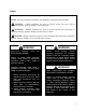
Safety Attention should be paid to the following statements: NOTE - Notes are intended to clarify the unit installation, operation and maintenance. CAUTION - Caution statements are given to prevent actions that may result in equipment damage, property damage, or personal injury. WARNING - Warning statements are given to prevent actions that could result in equipment damage, property damage, personal injury or death.
WARNING During installation, testing, servicing and troubleshooting of the equipment it may be necessary to work with live electrical components. Only a qualified licensed electrician or individual properly trained in handling live electrical components shall perform these tasks. Standard NFPA-70E, an OSHA regulation requiring an Arc Flash Boundary to be field established and marked for identification of where appropriate Personal Protective Equipment (PPE) be worn, should be followed.
CAUTION Rotation must be checked on all MOTORS AND COMPRESSORS of 3 phase units at startup by a qualified service technician. Scroll compressors are directional and can be damaged if rotated in the wrong direction. Compressor rotation must be checked using suction and discharge gauges. Fan motor rotation should be checked for proper operation.
WARNING Some chemical coil cleaning compounds are caustic or toxic. Use these substances only in accordance with the manufacturer’s usage instructions. Failure to follow instructions may result in equipment damage, injury or death. CAUTION Door compartments containing hazardous voltage or rotating parts are equipped with door latches to allow locks. Door latch are shipped with nut and bolts requiring tooled access.
WARNING COMPRESSOR CYCLING 5 MINUTE MINIMUM OFF TIME To prevent motor overheating compressors must cycle off for a minimum of 5 minutes. 5 MINUTE MINIMUM ON TIME To maintain the proper oil level compressors must cycle on for a minimum of 5 minutes. The cycle rate must not exceed 6 starts per hour. 1. The unit is for indoor use only. See General Information section for more unit information. 2. Every unit has a unique equipment nameplate with electrical, operational, and unit clearance specifications.
SB Base Model Description Model Number SB Series and Generation - 007 Unit Size - 3 Voltage BASE MODEL SERIES AND GENERATION SB UNIT SIZE 003 = 3 ton Capacity 004 = 4 ton Capacity 005 = 5 ton Capacity 006 = 6 ton Capacity 007 = 7 ton Capacity 009 = 9 ton Capacity 010 =10 ton Capacity 014 =14 ton Capacity 016 = 16 ton Capacity 018 = 18 ton Capacity VOLTAGE 1 = 230V/1Φ/60Hz 2 = 230V/3Φ/60Hz 3 = 460V/3Φ/60Hz 4 = 575V/3Φ/60Hz 8 = 208V/3Φ/60Hz 9 = 208V/1Φ/60Hz CONFIGURATION 0 = Right Hand Unit + Top Verti
SB Base Model and Features Description Model/Feature Number 0 0 0 B1 B2 B3 : 0 0 0 0 1A 1B 1C 1D Model Option B: HEATING B1: HEATING TYPE 0 = No Heating 3 = Electric Heat C = Steam Distributing Standard Coil D = Steam Distributing Polymer E-Coated Coil E = Hot Water Standard Coil F = Hot Water Polymer E-Coated Coil B2: HEATING DESIGNATION 0 = No Heating 1 = 1 Row Coil 2 = 2 Row Coil A = 7 kW (5.3 kW @ 208V) B = 14 kW (10.5 kW @ 208V) C = 21 kW (15.8 kW @ 208V) D = 28 kW (21.
SB Features Description Feature Number A B C 5A 5B 5C - 0 A 0 6A 6B 6C Feature 5: SUPPLY AIR OPTIONS 5A: SUPPLY AIR BLOWER CONFIGURATION 0 = No Airside - Condensing Unit Only A = 1 Blower + High Efficiency EC Motor B = 2 Blowers + High Efficiency EC Motors 5B: SUPPLY AIR BLOWER 0 = No Airside - Condensing Unit Only A = 310 mm (14”) Direct Drive Backward Curved Plenum Fan B = 355 mm (16”) Direct Drive Backward Curved Plenum Fan C = 450 mm (18”) Direct Drive Backward Curved Plenum Fan 5C: SUPPLY
SB Features Description Feature Number D 13 - E 0 14A 14B Feature 13: SPECIAL CONTROLS D = VAV Unit Controller - VAV Cool + CV Heat Y = VAV Single Zone Heat Pump Unit Controller VAV Cool + VAV Heat Z = Constant Volume Heat Pump Unit Controller CV Cool + CV Heat 1 = Make Up Air Heat Pump Unit Controller - CV Cool + CV Heat 4 = Field Installed DDC Controls by Others 5 = Field Installed DDC Controls by Others with Isolation Relays 6 = Factory Installed DDC Controls Furnished by Others with Isolation Rel
SB Features Description Feature Number 0 0 0 0 0 0 A B 16 17 18 19 20 21 22 23 Feature 16: INTERIOR CABINET OPTIONS 0 = Standard - Double Wall Construction + R-6.
General Information SB Series self contained units have been designed for indoor installation only. Units are assembled, wired, charged and runtested at the factory. WARNING Improper installation, adjustment, alteration, service or maintenance can cause property damage, personal injury or loss of life. Installation and service must be performed by a qualified installer. A copy of this IOM should be kept with the unit.
WARNING Failure to observe the following instructions will result in premature failure of your system and possible voiding of the warranty. Receiving Unit When received, the unit should be checked for damage that might have occurred in transit. If damage is found it should be noted on the carrier’s Freight Bill. A request for inspection by carrier’s agent should be made in writing at once.
All DX systems include evaporator coils, liquid line filter dryers, thermal expansion valves (TXV), and scroll compressors. Compressors are equipped with a positive pressure forced lubrication system. CAUTION CRANKCASE HEATER Some units are equipped with compressor crankcase heaters, which should be energized at least 24 hours prior to cooling operation, to clear any liquid refrigerant from the compressors.
Installation AAON equipment has been designed for quick and easy installation. Locating the Unit Placement of the unit relative to ductwork, electrical and plumbing must be carefully considered. Return air plenum or duct can be mounted directly to the return air flanges. Use flexible gasket material to seal the duct to the unit. Verify floor or foundation can support the total unit weight, including accessory weights.
SB Series Top View Compressor and Heat Exchanger Compartment Left Hand Side Supply Air Right Hand Side Return Air Connections and service access on right side for right hand orientation Air Flow Consider the air flow to be hitting the back of your head. Figure 3 - SB Series Unit Orientation Lifting and Handling the Unit Before lifting unit, be sure that all shipping material has been removed from unit.
Do not allow water containing any form of chlorides to enter this heat exchanger. Common forms of chlorides include: 1. Sea water mist entering an open cooling tower system. 2. Contaminated make-up water containing salt water. 3. Disinfection the water loop with solutions containing sodium hypochlorite. Chlorides will result in a premature failure of the condenser.
WARNING WATER FREEZING Failure of the condenser due to freezing will allow water to enter the refrigerant circuit and will cause extensive damage to the refrigerant circuit components. Any damage to the equipment as a result of water freezing in the condenser is excluded from coverage under AAON warranties and the heat exchanger manufacturer warranties. Unit is capable of operating with Entering Water Temperatures (EWT) as low as 57°F during cooling mode without the need for head pressure control.
Table 3 - Condenser Water Connections Supply and Return Connection Size Model (SB-) (in. FPT) 003, 004, 005 1 006, 007, 009, 010 1 1/4 014, 016, 018 1 1/2 Condenser water pump must be field sized and installed between the cooling tower or geothermal wellfield and self contained unit. System should be sized in accordance with the ASHRAE Handbook. Use engineering guidelines to maintain equal distances for supply and return piping and limit bend radiuses to maintain balance in the system.
Piping systems should not exceed 10 ft/sec fluid velocity to ensure tube wall integrity and reduce noise. Electrical Verify the unit nameplate agrees with power supply. SB Series units are provided with single point power wiring connections. Connection terminations are made to the main terminal block. A complete set of unit specific wiring diagrams, showing factory and field wiring are laminated in plastic and located inside the controls compartment door.
foam at the cut. The edges and corners that are not covered should then be sealed using silicone caulking or a duct seal compound. If a reciprocating saw is used to make the cut-out take care that the metal skins of the foam part do not separate from the foam, this would result in reduced structural integrity of the part. Size supply conductors based on the unit Minimum Current Ampacity (MCA) rating. Supply conductors must be rated a minimum of 75°C.
CAUTION Scroll compressors are directional and will be damaged by operation in the wrong direction. Low pressure switches on compressors have been disconnected after factory testing. Rotation should be checked by a qualified service technician at startup using suction and discharge pressure gauges and any wiring alteration should only be made at the unit power connection. Wire control signals to the unit’s low voltage terminal block located in the controls compartment.
Condensate Drain Piping Unit may be equipped with more than one condensate drain pan connection. A p-trap and drain line must be installed on at least one section’s drain connection, with the ptrap not to exceed 6” from the drain connection. The lines should be the same pipe size or larger than the drain connection, include a p-trap, and pitch downward toward drain. An air break should be used with long runs of condensate lines. CAUTION Unit should not be operated without p-traps.
The waterside economizer circuit can operate in three modes: waterside economizer only, waterside economizer with mechanical cooling, and mechanical cooling only. corrosion. Never use hydrochloric acid (muriatic acid) or chlorine as it will corrode stainless steel. During waterside economizer only mode of operation condenser water flows through the waterside economizer coil with modulating valves maintaining supply air temperature setpoint. The condenser water then passes through water-cooled condenser.
WARNING Electric shock hazard. Shut off all electrical power to the unit to avoid shock hazard or injury from rotating parts. During startup, it is necessary to perform routine checks on the performance of the unit. This includes checking of the air flow, the air filters, condenser water flow and refrigerant charge. Supply Fans SB Series units are equipped with direct drive backward curved plenum supply fan assemblies that deliver the air volume specified according to unit size and job requirements.
Figure 6 - ECM with Factory Provided Controls Figure 7 - ECM with Potentiometer Control 29
Figure 8 - ECM with Field Installed Controls 30
Filters Do not operate the unit without filters in place. Unit should be checked for correct filter placement during startup. Operation of the equipment without filters will result in a clogged evaporator coil. CAUTION Before completing startup and leaving the unit a complete operating cycle should be observed to verify that all components are functioning properly.
Subtract the saturated temperature from the measured suction line temperature to determine the evaporator superheat. Compare calculated superheat to the table below for the appropriate unit type and options. CAUTION DO NOT OVERCHARGE! Refrigerant overcharging leads to excess refrigerant in the condenser coils resulting in elevated compressor discharge pressure.
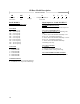
Table 7 - R-410A Refrigerant Temperature-Pressure Chart °F 20 21 22 23 24 25 26 27 28 29 30 31 32 33 34 35 36 37 38 39 40 41 42 43 44 45 46 PSIG 78.3 80.0 81.8 83.6 85.4 87.2 89.1 91.0 92.9 94.9 96.8 98.8 100.9 102.9 105.0 107.1 109.2 111.4 113.6 115.8 118.1 120.3 122.7 125.0 127.4 129.8 132.2 °F 47 48 49 50 51 52 53 54 55 56 57 58 59 60 61 62 63 64 65 66 67 68 69 70 71 72 73 PSIG 134.7 137.2 139.7 142.2 144.8 147.4 150.1 152.8 155.5 158.2 161.0 163.8 166.7 169.6 172.5 175.4 178.4 181.5 184.5 187.6 190.
Operation through the steam or hot water coil assembly. Unit operations should be controlled with thermostat or unit controller, never at the main power supply, except for emergency or complete shutdown of the unit. Packaged DX Cooling Operation and Control When a call for cooling is made the supply fan motors and compressors will energize. WARNING COMPRESSOR CYCLING 5 MINUTE MINIMUM OFF TIME To prevent motor overheating compressors must cycle off for a minimum of 5 minutes.
Cleaning of the drain pans and inside of the unit should be done only by qualified personnel. E-Coated Coil Cleaning Documented routine cleaning of e-coated coils is required to maintain coating warranty coverage. WARNING Electric shock hazard. Shut off all electrical power to the unit to avoid shock hazard or injury from rotating parts. Surface loaded fibers or dirt should be removed prior to water rinse to prevent restriction of airflow.
dust, soot, greasy residue, lint and other particulate: Enviro-Coil Concentrate, Part Number HEC01. Recommended Chloride Remover CHLOR*RID DTS™ should be used to remove soluble salts from the e-coated coil, but the directions must be followed closely. This product is not intended for use as a degreaser. Any grease or oil film should first be removed with the approved cleaning agent. Remove Barrier - Soluble salts adhere themselves to the substrate.
Filter Replacement Monthly filter inspection is required to maintain optimum unit efficiency. WARNING Electric shock hazard. Shut off all electrical power to the unit to avoid shock hazard or injury from rotating parts. It is strongly recommended that filter media be replaced monthly. Filters are located upstream of the evaporator coil. Open access panel and pull filters straight out to inspect all of the filters. Replace filters with the size indicated on each filter.
Feature 6A 0 A Feature 6B 0 A B C D E Filter Type Pre Filters High Efficiency Filters Secondary High Efficiency Filters Filter Type Pre Filters High Efficiency Filters Secondary High Efficiency Filters Filter Type Pre Filters High Efficiency Filters Secondary High Efficiency Filters 38 Table 10 - 14-18 ton (D Cabinet) Pre and Unit Filters Quantity/Size Type No Pre Filters 4/18” x 24” x 2” Pleated, 30% Eff, MERV 8 Quantity/Size Type No Standard Filters 4/18” x 24” x 2” Pleated, 30% Eff, MERV 8 Pleated, 30%
Appendix A - Heat Exchanger Corrosion Resistance The resistance guide below provides the corrosion resistance of stainless steel type AISI 316 and pure Copper (99.9%) in water, to a number of important chemical factors. The actual corrosion is a very complex process influenced by many different factors in combination.
Water Containing Total Hardness (°dH) Nitrate (NO3) Iron (Fe) Aluminum (Al) Manganese (Mn) Chloride Content = 10 ppm = 25 ppm = 50 ppm = 80 ppm = 150 ppm = 300 ppm > 300 ppm 40 Concentration (mg/l or ppm) Time Limits Analyze Before AISI 316 SMO 254 Copper Alloy Nickel Alloy 4.0-8.5 No Limit + + + + + + + + + + + + + + + + + + + + + 0 + 0 + 0 + 0 + + + + + + + + < 100 > 100 < 0.2 > 0.2 < 0.2 > 0.2 < 0.1 > 0.
SB Series Startup Form Job Name:_______________________________________________ Date:______________ Address:______________________________________________________________________ ______________________________________________________________________________ Model Number:_________________________________________________________________ Serial Number:_____________________________________________ Tag:_______________ Startup Contractor:______________________________________________________________ Address:___
Supply Fan Assembly Alignment Number Check Rotation hp Nameplate Amps________ L1 L2 L3 1 2 VAV Controls_________________ Compressors/DX Cooling Check Rotation Number L1 L2 L3 Head Pressure PSIG Suction Pressure PSIG Line Temperature Sub-cooling Superheat N/A N/A N/A Sub-cooling Superheat N/A N/A N/A 1 Refrigeration System 1 - Cooling Mode Saturated Pressure Temperature Discharge Suction Liquid Refrigeration System 1 - Heating Mode (Heat Pump Only) Saturated Line Pressure Temperature Te
Water/Glycol System 1. Has the entire system been flushed and pressure checked? Yes No 2. Has the entire system been filled with fluid? Yes No 3. Has air been bled from the heat exchangers and piping? Yes No 4. Is the glycol the proper type and concentration (N/A if water)? Yes No 5. Is there a minimum load of 50% of the design load? Yes No 6. Has the water piping been insulated? Yes No 7.
Maintenance Log This log must be kept with the unit. It is the responsibility of the owner and/or maintenance/service contractor to document any service, repair or adjustments. AAON Service and Warranty Departments are available to advise and provide phone help for proper operation and replacement parts. The responsibility for proper startup, maintenance, and servicing of the equipment falls to the owner and qualified licensed technician. Entry Date 44 Action Taken Name/Tel.
Literature Change History November 2012 First Revision, Rev. A, of the SB Series IOM. December 2012 Manual updated with the voltage options corrected, option 1 = 230V/1Φ/60Hz and option 9 = 208V/1Φ/60Hz. Condensing unit only options and ECM driven fan airflow adjustment information added.
AAON 2425 South Yukon Ave. Tulsa, OK 74107-2728 Phone: 918-583-2266 Fax: 918-583-6094 www.aaon.com SB Series Installation, Operation & Maintenance V14190 · Rev. A · 121227 (ACP 31227) It is the intent of AAON to provide accurate and current product information. However, in the interest of product improvement, AAON reserves the right to change pricing, specifications, and/or design of its product without notice, obligation, or liability. Copyright © AAON, all rights reserved throughout the world.