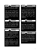
LN Series Chillers and Outdoor Mechanical Rooms Installation, Operation, & Maintenance WARNING FIRE OR EXPLOSION HAZARD Failure to follow safety warnings exactly could result in serious injury, death or property damage. Be sure to read and understand the installation, operation and service instructions in this manual. Improper installation, adjustment, alteration, service or maintenance can cause serious injury, death or property damage. A copy of this IOM should be kept with the unit.
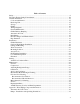
Table of Contents Safety .............................................................................................................................................. 6 LN Series Feature String Nomenclature ....................................................................................... 10 General Information ...................................................................................................................... 15 Codes and Ordinances ..................................................
Pump Piping - General .............................................................................................................. 39 Pump Operation......................................................................................................................... 40 General Care .............................................................................................................................. 41 Dual Pump Specific Information................................................................
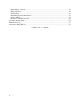
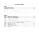
Index of Tables and Figures Tables: Table 1 - Service Clearances......................................................................................................... 19 Table 2 - Mounting Dimensions ................................................................................................... 20 Table 3 - Return/Exhaust Fan Pin Location .................................................................................. 27 Table 4 - Return/Exhaust Fan Pin Location ....................................
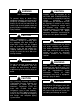
Safety Attention should be paid to the following statements: NOTE - Notes are intended to clarify the unit installation, operation and maintenance. CAUTION - Caution statements are given to prevent actions that may result in equipment damage, property damage, or personal injury. WARNING - Warning statements are given to prevent actions that could result in equipment damage, property damage, personal injury or death.
WARNING FIRE, EXPLOSION OR CARBON MONOXIDE POISONING HAZARD Failure to replace proper controls could result in fire, explosion or carbon monoxide poisoning. Failure to follow safety warnings exactly could result in serious injury, death or property damage. Do not store or use gasoline or other flammable vapors and liquids in the vicinity of this appliance. WARNING Electric shock hazard.
WARNING UNIT HANDLING To prevent injury or death lifting equipment capacity shall exceed unit weight by an adequate safety factor. Always test-lift unit not more than 24 inches high to verify proper center of gravity lift point to avoid unit damage, injury or death. CAUTION Door compartments containing hazardous voltage or rotating parts are equipped with door latches to allow locks. Door latch are shipped with nut and bolts requiring tooled access.
CAUTION Polyolester (POE) and Polyvinylether (PVE) oils are two types of lubricants used in hydrofluorocarbon (HFC) refrigeration systems. Refer to the compressor label for the proper compressor lubricant type. PROVIDED MANUAL. THROUGHOUT THIS 5. Keep this manual and all literature safeguarded near or on the unit. WARNING COMPRESSOR CYCLING 5 MINUTE MINIMUM OFF TIME To prevent motor overheating compressors must cycle off for a minimum of 5 minutes.
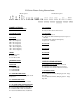
LN Series Feature String Nomenclature 10A 10B 10C 10D 9 8A 8B 8C 6 7 5A 5B 5C 5D 4A 4B 4C 4D 3A 3B 3C 3D Unit Feature Options 1 2 : B1 B2 B3 B4 A1 A2 A3 A4 A5 VLT MNREV SERIES SIZE MJREV GEN Model Options LN A – 140 – C – 0 – 3 – C A C 0 E – 0 0 0 0 : A 0 – 0 0 0 0 – 0 0 0 0 – 0 0 0 0 – 0 0 – 0 0 0 – 0 – 0 E 0 0 – MODEL OPTIONS SERIES AND GENERATION LN MAJOR REVISION A UNIT SIZE 045 = 45 ton Capacity 055 = 55 ton Capacity 060 = 60 ton Capacity 075 = 75 ton Capacity 095 = 95 ton Capacity
LN Series Feature String Nomenclature 10A 10B 10C 10D 9 8A 8B 8C 6 7 5A 5B 5C 5D 4A 4B 4C 4D 3D 3A 3B 3C Unit Feature Options 1 2 : B1 B2 B3 B4 A1 A2 A3 A4 A5 VLT MNREV SERIES SIZE MJREV GEN Model Options 3A: BUILDING PUMP CONFIGURATION 0 = No Building Pumps A = 1 Pump + High Eff Motor B = 1 Dual Pump + High Eff Motors D = 1 Pump + VFD + High Eff Motor E = 1 Dual Pump + 2 VFD's + High Eff Motors K = 1 Pump + Field Installed VFD + High Eff Motor L = 1 Dual Pump + 2 Field Installed VFD's
LN Series Feature String Nomenclature 10D 10A 10B 10C 9 8A 8B 8C 6 7 5A 5B 5C 5D 4A 4B 4C 4D 3D 3A 3B 3C Unit Feature Options 1 2 : B1 B2 B3 B4 A1 A2 A3 A4 A5 VLT MNREV SERIES SIZE MJREV GEN Model Options 3D: BUILDING PUMP MOTOR SIZE 0 = No Building Pumps C = 1 hp E = 2 hp F = 3 hp G = 5 hp H = 7.
LN Series Feature String Nomenclature 10D 10A 10B 10C 9 8A 8B 8C 6 7 5A 5B 5C 5D 4A 4B 4C 4D 3A 3B 3C 3D Unit Feature Options 1 2 : B1 B2 B3 B4 A1 A2 A3 A4 A5 VLT MNREV SERIES SIZE MJREV GEN Model Options LN A – 140 – C – 0 – 3 – C A C 0 E – 0 0 0 0 : A 0 – 0 0 0 0 – 0 0 0 0 – 0 0 0 0 – 0 0 – 0 0 0 – 0 – 0 E 0 0 – 10D: BMS CONNECTION & DIAGNOSTICS 0 = None A = BACnet IP B = BACnet MSTP C = Modbus IP D = Modbus RTU E = Lontalk H = No BMS Connection with Diagnostics J = BACnet IP with Dia
LN Series Feature String Nomenclature 10A 10B 10C 10D 9 8A 8B 8C 6 7 5A 5B 5C 5D 4A 4B 4C 4D 3A 3B 3C 3D Unit Feature Options 1 2 : B1 B2 B3 B4 A1 A2 A3 A4 A5 VLT MNREV SERIES SIZE MJREV GEN Model Options LN A – 140 – C – 0 – 3 – C A C 0 E – 0 0 0 0 : A 0 – 0 0 0 0 – 0 0 0 0 – 0 0 0 0 – 0 0 – 0 0 0 – 0 – 0 E 0 0 – 26D: BLANK 0 = Standard 26E: BLANK 0 = Standard 26F: BLANK 0 = Standard 27: BLANK 0 = Standard 28: BLANK 0 = Standard 29: BLANK 0 = Standard 30: BLANK 0 = Standard 31: BLANK 0
General Information AAON LN Series chillers are complete selfcontained liquid chilling units. They are assembled, wired, charged and run-tested. Models are available for air-cooled applications. Chiller primary pumping packages are available as optional features. WARNING Improper installation, adjustment, alteration, service or maintenance can cause property damage, personal injury or loss of life. Startup and service must be performed by a Factory Trained Service Technician.
when power is restored if liquid enters the compressor. Chiller WARNING COMPRESSOR CYCLING 5 MINUTE MINIMUM OFF TIME To prevent motor overheating compressors must cycle off for a minimum of 5 minutes. 5 MINUTE MINIMUM ON TIME To maintain the proper oil level compressors must cycle on for a minimum of 5 minutes. The cycle rate must not exceed 6 starts per hour. Failure to observe the following instructions will result in premature failure of your system, and possible voiding of the warranty.
Scroll compressors must be on a minimum of 5 minutes and off for a minimum of 5 minutes. The cycle rate must be no more than 6 starts per hour. The chiller is furnished with a pressure differential switch that is factory installed between the chilled water supply and return connections. This sensor must not be bypassed since it provides a signal to the unit controller that water flow is present in the heat exchanger and the unit can operate without the danger of freezing the liquid.
Dual Pumps When redundant pumping is required, factory installed dual pumps can be ordered. A dual pump is a pump with two independent motors and pumps in a single casing. This dual pump has a swing splitflapper valve in the discharge port to prevent liquid recirculation when only one pump is operating. Isolation valves in the casing allow one pump to be isolated and removed for service while the other pump is still operating. The controls package will activate the pump when the unit is given a run command.
Installation Chiller Placement The AAON LN Series is designed for outdoor applications and mounting at ground level or on a rooftop. It must be placed on a level and solid foundation that has been prepared to support its weight. The placement relative to the building air intakes and other structures must be carefully selected. Be sure to observe the dimensions that are on the rating plate of the chiller for operational and service clearances.
Figure 3 - Lifting Points Figure 2 - Steel Mounting Rail with Dimensions Table 2 - Mounting Dimensions Tons A B C 45-140 142” 138” 134” D 139” Lifting and Handling If cables or chains are used to hoist the unit they must be the same length and care should be taken to prevent damage to the cabinet. See Figure 4 for additional information. Before lifting unit, be sure that all shipping material has been removed from unit. Secure hooks and cables at all lifting points/ lugs provided on the unit.
Figure 4 - Lifting Detail of a 45-75 ton Unit Figure 5 - Lifting Detail of a 95-140 ton Unit Lifting slot locations are unit specific. Unit must be rigged at all marked lifting points.
Water Connection Connect the supply and return water lines. The connection size is listed on the unit rating sheet, along with the designed volumetric flow rate. The maximum operating pressure for AAON LN Series units is 125 psi. CAUTION PVC (Polyvinyl Chloride) and CPVC (Chlorinated Polyvinyl Chloride) are vulnerable to attack by certain chemicals.
Low Ambient Operation If the chiller is ordered for a Low Ambient application, the liquid system must use a glycol solution and the piping must be insulated to be prepared for freezing conditions. Care must be taken in the source of electrical power for the heating tape and thermostat. Electrical The single point electrical power connections are made in the electrical control compartment. WARNING Electric shock hazard.
may be a function of the variable frequency drive and must not be bypassed. Note: All units are factory wired for 208/230V, 460V, or 575V. If unit is to be connected to a 208V supply, the transformer must be rewired to 208V service. For 208V service interchange the yellow and red conductor on the low voltage control transformer. Red-Black for 208V Yellow-Black for 230V Wire control signals to the unit’s low voltage terminal block located in the controls compartment.
Startup (See back of the manual for startup form) Use the general check list at the top of the startup form to make a last check that all the components are in place, water flow is present, and the power supply is energized. WARNING Electric shock hazard. Shut off all electrical power to the unit to avoid shock hazard or injury from rotating parts. WARNING Improper installation, adjustment, alteration, service, or maintenance can cause property damage, personal injury, or loss of life.
Axial Flow Condenser Fans Multi-Wing Z Series Aluminum Fan Blade Pitch Angle Setting Instructions 1. Maintain the balance of fan Mark the hub castings across a joint, so the fan hub can be reassembled in the same orientation. Mark the location of any balancing weight. Balancing weight will be on the outer bolt circle, in the form of washers, and/or longer bolts, or an additional balancing nut. Number the blades and blade sockets, so that they are replaced into their original position.
5. Determine whether the pin is in the HUB or RET Figure 11 - Fan HUB and RET Castings 6. Determine the current blade pitch and the pin location for the new blades Type 5Z Bushing Mount A B Type Rot.
Multi-Wing W Series Black Glass Reinforced Polypropylene Fan Blade Pitch Angle Setting Instructions Contact the AAON parts department to acquire the new pitch pins for the fan blades. Note original position of retaining plates, center boss and all hardware including additional hardware used for balancing. 1. Remove all the bolts and nuts. 2. Determine blade rotation – on the concave side of the blade is a blade marking showing 6WR, 6WL, 7WL, 7WR, or 9WR. The “L” and “R” denote the rotation of the blade. 3.
Maintenance CAUTION General Qualified technicians must perform routine service checks and maintenance. This includes reading and recording the condensing and suction pressures and checking for normal sub-cooling and superheat. Air-cooled condenser units require maintenance schedules/procedures. Unit specific instructions are included in this manual. Compressors The scroll compressors are fully hermetic and require no maintenance except keeping the shell clean.
Convert the pressure obtained to a saturated temperature using the appropriate refrigerant temperature-pressure chart. Subtract the measured liquid line temperature from the saturated temperature to determine the liquid sub-cooling. Compare calculated sub-cooling to the table below for the appropriate unit type and options. Checking Evaporator Superheat Measure the temperature of the suction line close to the compressor. Read gauge pressure at the suction line close to the compressor.
Correct an undercharged system by adding refrigerant to the system to reduce superheat and raise sub-cooling. If the sub-cooling is correct and the superheat is too high, the expansion valve may need adjustment to correct the superheat.
Table 7 - R-410A Refrigerant Temperature-Pressure Chart 32 F psig F psig F psig F psig F psig 20 78.3 50 142.2 80 234.9 110 364.1 140 540.1 21 80.0 51 144.8 81 238.6 111 369.1 141 547.0 22 81.8 52 147.4 82 242.3 112 374.2 142 553.9 23 83.6 53 150.1 83 246.0 113 379.4 143 560.9 24 85.4 54 152.8 84 249.8 114 384.6 144 567.9 25 87.2 55 155.5 85 253.7 115 389.9 145 575.1 26 89.1 56 158.2 86 257.5 116 395.2 146 582.3 27 91.
Lubrication All original motors and bearings are furnished with an original factory charge of lubrication. Certain applications require bearings be re-lubricated periodically. The schedule will vary depending on operating duty, temperature variations, or severe atmospheric conditions. Bearings should be re-lubricated at normal operating temperatures, but not when running. Rotate the fan shaft by hand and add only enough grease to purge the seals. DO NOT OVERLUBRICATE.
A monthly clean water rinse is recommended for coils that are applied in coastal or industrial environments to help to remove chlorides, dirt, and debris. It is very important when rinsing, that water temperature is less than 130°F and pressure is than 900 psig to avoid damaging the fin edges. An elevated water temperature (not to exceed 130°F) will reduce surface tension, increasing the ability to remove chlorides and dirt.
the entire area to be cleaned is wetted. After the substrate has been thoroughly wetted, the salts will be soluble and is now only necessary to rinse them off. Rinse - It is highly recommended that a hose be used, as a pressure washer will damage the fins. The water to be used for the rinse is recommended to be of potable quality, though a lesser quality of water may be used if a small amount of CHLOR*RID DTS is added. Check with CHLOR*RID International, Inc.
Appendix - Water Piping Component Information Automatic Air Vent Valves Automatic Air Vent Valves provide automatic air venting for hot or cold water distribution systems. These vents purge air that may be in the water system. The vent valve utilizes a float to actuate the valve plug which is located at the top of the valve. Once the air is displaced and the system pressure is sustained, the valve plug seals and prevents any water from escaping from the system.
of at least 1⁄2" diameter between the “Float Vent” valves and installation. Installation When the air vent valve is installed as shown, the air will not be vented while the fluid is circulating in the system, but it can vent when the system is shut off. While the air vent valve is in operation, back off the small vent cap two turns. This is the proper operating setting which will allow air to be vented from the system. It is advisable to leave the cap on to prevent impurities from entering the valve.
Dimensions – Weights: Pumps - Installation and Operating Instructions Introduction This document contains specific information regarding the safe installation, operating, and maintenance of Vertical In-Line pumps and should be read and understood by installing, operating, and maintenance personnel. The equipment supplied has been designed and constructed to be safe and without risk to health and safety when properly installed, operated, and maintained.
rotating element free and bearings fully functional. Vertical Inline Positioning: Pump Lifting Strap For long term storage, the pump must be placed in a vertical position in a dry environment. Internal rusting can be prevented by removing the plugs at the top and bottom of the casing and drain or air blow out all water to prevent rust buildup or the possibility of freezing. Be sure to reinstall the plugs when the unit is made operational.
Alignment Alignment is unnecessary on close-coupled pumps as there is no shaft coupling. Split-coupled units are accurately aligned at the factory prior to being shipped and do not need re-aligning when installed. Pump Operation CAUTION Do not run pumps with discharge valve closed or under very low flow conditions. Starting Pump Ensure that the pump turns freely by hand, or with some mechanical help such as a strap and lever on larger pumps.
Check rotation arrow prior to operating the unit. The rotation of all Vertical In-Line units is “clockwise” when viewed from the drive end. (Looking from on top of / behind the motor) General Care Vertical In-Line pumps are built to operate without periodic maintenance, other than motor lubrication on larger units.
Mechanical seals may ‘weep’ slightly at start-up. Allow the pump to continue operating for several hours and the mechanical seal to ‘seat’ properly prior to calling for service personnel. System Cleanliness Before starting the pump the system must be thoroughly cleaned, flushed and drained and replenished with clean liquid. Welding slag and other foreign materials, “Stop Leak” and cleaning compounds and improper or excessive water treatment are all detrimental to the pump internals and sealing arrangement.
Vibration Levels Vertical In-Line pumps are designed to meet vibration levels set by Hydraulic Institute Standard HI Pump Vibration 9.6.4. Standard levels are as detailed below: Dual Pump Specific Information Dual Pump Flapper Valve Operating Instructions This unit is fitted with internal valves to allow isolation of one pump for service and to automatically prevent recirculation of the flow when only one pump is running.
Discharge Valve This valve performs the dual function of automatically sealing the discharge of the inactive pump when one pump is running and can manually be closed and locked to isolate one pump for service. Automatic Flapper Operation In the flapper mode the two halves of the discharge valve are free to pivot independently under normal operating conditions.
Locking 1. Loosen suction side set screw (11) to release the locking handle (3). 2. Rotate the suction side locking handle (3) so that the handle points towards the pump to be serviced and secure in the horizontal position, using set screw (11). This releases the suction locking arm (4). Note: The locking handle (3) should only be rotated towards the pump stopped for service.
Suction Guides Introduction Suction Guides are designed for bolting directly onto the suction flange of horizontal or vertical shaft centrifugal pumps. Operating Limits The suction guide is designed to be a fourfunction fitting. Each Suction Guide is a 90º elbow, a Pipe Strainer and a Flow Stabilizer. It may also be used as a Reducing Elbow, should the suction piping be larger than the pump inlet.
systems and could easily clog with debris if left in place. This will be detrimental to the operation of the pump. Inspect the cover O-ring and replace if necessary. Replace the permanent strainer into the fitting body, once the temporary strainer is removed. Replace the cover into the body. Ensuring that the strainer is properly seated, tighten the cover bolts diagonally, evenly and firmly.
The gasket cavity should face out to the adjoining flange. 6. Flange gaskets are not interchangeable with other mechanical pipe couplings or flange gaskets. 2. Lubricate the inner and outer diameter of the gasket with the lubricant provided or a similar non-petroleum based water soluble grease. 3. Press the gasket firmly into the flange cavity ensuring that the sealing lip is pointed outward. When in place, the gasket should not extend beyond the end of the pipe (as shown).
Step 2. With valve in fully open position, locate the differential pressure on the Performance curve, and for the given valve size in use, read the corresponding flow rate. Flow Measurement with the valve in the throttled position Step 1. The valve stem with its grooved rings and positioning sleeve is the flow indicator scale for the throttled position of the valve. Step 3. Measure and record the differential pressure across the valve in the throttled position. Step 4.
Note: To prevent premature valve failure it is not recommended that the valve operate in the throttled position with more than 25 ft pressure differential. Instead the pump impeller should be trimmed or valves located elsewhere in the system to partially throttle the flow. Operation To assure tight shut-off, the valve must be closed using a wrench with 25 to 30 ft-lbs of torque.
Pressure-Temperature Limits Flo-Trex Cross Section 1. Body Main 2. Eye Bolt 3. Shaft 4. Spring 5. Spacer 6. Disc 7. Seat 8. O ring body 9. Body Suction 10. Capscrew 12. O ring 13. Bonnet 14.
LN Series Startup Form Job Name:_______________________________________________ Date:______________ Address:______________________________________________________________________ ______________________________________________________________________________ Model Number:_________________________________________________________________ Serial Number:_____________________________________________ Tag:_______________ Startup Contractor:______________________________________________________________ Address:___
Water/Glycol System 1. Has the entire system been flushed and pressure checked? Yes No 2. Have isolation valves to the chiller been installed? Yes No 3. Has the entire system been filled with fluid? Yes No 4. Has air been bled from the heat exchangers and piping? Yes No 5. Is there a minimum load of 50% of the design load? Yes No 6. Has the water piping been insulated? Yes No 7. Is the glycol the proper type and concentration (N/A if water)? Yes No 8.
Condenser Fans Alignment Number hp Check Rotation L1 Nameplate Amps________ L2 L3 1 2 3 4 5 6 7 8 Pumping Package hp Chiller Building Pump #1 Chiller Building Pump #2 56 L1 L2 L3 Flow (gpm)
Maintenance Log This log must be kept with the unit. It is the responsibility of the owner and/or maintenance/service contractor to document any service, repair or adjustments. AAON Service and Warranty Departments are available to advise and provide phone help for proper operation and replacement parts. The responsibility for proper start-up, maintenance and servicing of the equipment falls to the owner and qualified licensed technician. Entry Date Action Taken Name/Tel.
Literature Change History February 2014 Initial version.
AAON 2425 South Yukon Ave. Tulsa, OK 74107-2728 Phone: 918-583-2266 Fax: 918-583-6094 www.aaon.com LN Series Installation, Operation, & Maintenance V28980 · Rev. A · 140225 It is the intent of AAON to provide accurate and current product information. However, in the interest of product improvement, AAON reserves the right to change pricing, specifications, and/or design of its product without notice, obligation, or liability. Copyright © AAON, all rights reserved throughout the world.