LL Series Chillers and Outdoor Mechanical Rooms Installation, Operation & Maintenance WARNING FIRE OR EXPLOSION HAZARD Failure to follow safety warnings exactly could result in serious injury, death or property damage. Be sure to read and understand the installation, operation and service instructions in this manual. Improper installation, adjustment, alteration, service or maintenance can cause serious injury, death or property damage. A copy of this IOM should be kept with the unit.
Table of Contents Safety .............................................................................................................................................. 7 LL Series Feature String Nomenclature ....................................................................................... 11 General Information ...................................................................................................................... 19 Codes and Ordinances ..................................................
E-Coated Coil Cleaning ............................................................................................................ 47 Recommended Coil Cleaner .................................................................................................. 48 Recommended Chloride Remover ......................................................................................... 48 Evaporative-Cooled Condenser.................................................................................................
Horizontal and Vertical Expansion Tanks ................................................................................ 72 Suction Guides .......................................................................................................................... 73 Glycol Auto Fill Unit ................................................................................................................ 74 Flo-Trex Combination Valve ..................................................................................
Index of Tables and Figures Tables: Table 1 - Service Clearances......................................................................................................... 26 Table 2 - Mounting Dimensions ................................................................................................... 27 Table 3 - Boiler Rated Input Capacity .......................................................................................... 29 Table 4 - Condenser Flooding..............................................
Safety Attention should be paid to the following statements: NOTE - Notes are intended to clarify the unit installation, operation and maintenance. CAUTION - Caution statements are given to prevent actions that may result in equipment damage, property damage, or personal injury. WARNING - Warning statements are given to prevent actions that could result in equipment damage, property damage, personal injury or death.
WARNING FIRE, EXPLOSION OR CARBON MONOXIDE POISONING HAZARD Failure to replace proper controls could result in fire, explosion or carbon monoxide poisoning. Failure to follow safety warnings exactly could result in serious injury, death or property damage. Do not store or use gasoline or other flammable vapors and liquids in the vicinity of this appliance. WARNING Electric shock hazard.
WARNING UNIT HANDLING To prevent injury or death lifting equipment capacity shall exceed unit weight by an adequate safety factor. Always test-lift unit not more than 24 inches high to verify proper center of gravity lift point to avoid unit damage, injury or death. WARNING Always use a pressure regulator, valves and gauges to control incoming pressures when pressure testing a system. Excessive pressure may cause line ruptures, equipment damage or an explosion which may result in injury or death.
WARNING Some chemical coil cleaning compounds are caustic or toxic. Use these substances only in accordance with the manufacturer’s usage instructions. Failure to follow instructions may result in equipment damage, injury or death. CAUTION Door compartments containing hazardous voltage or rotating parts are equipped with door latches to allow locks. Door latch are shipped with nut and bolts requiring tooled access.
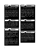
LL Series Feature String Nomenclature 15 16 17 18 19 20 21 22 23 14A 14B 7 8 9 10 11 12 13 6A 6B 6C 5A 5B 5C 2 3 4 Unit Feature Options 1A 1B 1C 1D : B1 B2 B3 A1 A2 A3 A4 CONFIG VLT SIZE GEN Model Options L L – 0 7 5 – 3 – 0 – D B 0 A – A 2 C : C R J G – 0 F B – K 5 E – K J G – A 0 C 0 C B A – E C – 0 F AA 0 0 B 0 B BASE MODEL SERIES AND GENERATION LL UNIT SIZE 035 = 35 ton Capacity 050 = 50 ton Capacity 055 = 55 ton Capacity 060 = 60 ton Capacity 067 = 67 ton Capacity 075 = 75 ton Capacity
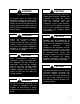
LL Series Feature String Nomenclature 15 16 17 18 19 20 21 22 23 14A 14B 7 8 9 10 11 12 13 6A 6B 6C 5A 5B 5C 2 3 4 Unit Feature Options 1A 1B 1C 1D : B1 B2 B3 A1 A2 A3 A4 CONFIG VLT SIZE GEN Model Options L L – 0 7 5 – 3 – 0 – D B 0 A – A 2 C : CR J G – 0 F B – K 5 E – K J G – A 0 C 0 C B A – E C – 0 F AA 0 0 B 0 B MODEL OPTION B: HEATING B1: HEATING TYPE 0 = No Boiler A = Natural Gas Fired Boiler B = Propane Fired Boiler B2: BOILER QUANTITY 0 = No Boiler 1 = 1 Boiler 2 = 2 Boilers 3 = 3 Boi
LL Series Feature String Nomenclature 15 16 17 18 19 20 21 22 23 14A 14B 7 8 9 10 11 12 13 6A 6B 6C 5A 5B 5C 2 3 4 Unit Feature Options 1A 1B 1C 1D : B1 B2 B3 A1 A2 A3 A4 CONFIG VLT SIZE GEN Model Options L L – 0 7 5 – 3 – 0 – D B 0 A – A 2 C : C R J G – 0 F B – K 5 E – K J G – A 0 C 0 C B A – E C – 0 F AA 0 0 B 0 B 1C: PUMP SIZE 0 = Standard - No Building Pump A = Pump 4360 1.5B B = Pump 4360 2B C = Pump 4360 2D D = Pump 4380 1.5x1.
LL Series Feature String Nomenclature 15 16 17 18 19 20 21 22 23 14A 14B 7 8 9 10 11 12 13 6A 6B 6C 5A 5B 5C 2 3 4 Unit Feature Options 1A 1B 1C 1D : B1 B2 B3 A1 A2 A3 A4 CONFIG VLT SIZE GEN Model Options L L – 0 7 5 – 3 – 0 – D B 0 A – A 2 C : C R J G – 0 F B – K 5 E – K J G – A 0 C 0 C B A – E C – 0 F AA 0 0 B 0 B FEATURE 4: LOW AMBIENT 0 = Standard - None A = One Refrigerant Circuit B = Two Refrigerant Circuits C = Three Refrigerant Circuits D = Four Refrigerant Circuits E = Five Refriger
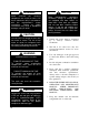
LL Series Feature String Nomenclature 15 16 17 18 19 20 21 22 23 14A 14B 7 8 9 10 11 12 13 6A 6B 6C 5A 5B 5C 2 3 4 Unit Feature Options 1A 1B 1C 1D : B1 B2 B3 A1 A2 A3 A4 CONFIG VLT SIZE GEN Model Options L L – 0 7 5 – 3 – 0 – D B 0 A – A 2 C : C R J G – 0 F B – K 5 E – K J G – A 0 C 0 C B A – E C – 0 F AA 0 0 B 0 B FEATURE 6: BOILER BUILDING PUMP 6A: PUMP CONFIGURATION 0 = Standard - No Boiler D = 1 Pump - Prem Eff, 1170 RPM E = 2 Single Pumps - Prem Eff, 1170 RPM F = dualArm Pump - Prem Ef
LL Series Feature String Nomenclature 15 16 17 18 19 20 21 22 23 14A 14B 7 8 9 10 11 12 13 6A 6B 6C 5A 5B 5C 2 3 4 Unit Feature Options 1A 1B 1C 1D : B1 B2 B3 A1 A2 A3 A4 CONFIG VLT SIZE GEN Model Options L L – 0 7 5 – 3 – 0 – D B 0 A – A 2 C : C R J G – 0 F B – K 5 E – K J G – A 0 C 0 C BA – E C – 0 F AA 0 0 B 0 B FEATURE 8: REFRIGERATION OPTIONS 0 = Standard B = VFD Controlled Condenser Fans (Air-Cooled) D = Hot Gas Bypass - All Circuits E = Options B + D FEATURE 12: CONTROLS 0 = Standard
LL Series Feature String Nomenclature 15 16 17 18 19 20 21 22 23 14A 14B 7 8 9 10 11 12 13 6A 6B 6C 5A 5B 5C 2 3 4 Unit Feature Options 1A 1B 1C 1D : B1 B2 B3 A1 A2 A3 A4 CONFIG VLT SIZE GEN Model Options L L – 0 7 5 – 3 – 0 – D B 0 A – A 2 C : C R J G – 0 F B – K 5 E – K J G – A 0 C 0 C B A – EC – 0 FAA 0 0 B 0 B FEATURE 14: COMPRESSION TANK FEATURE 15: OPTION BOXES 14A: CHILLER COMPRESSION TANK 0 = No Chiller Compression Tank A = AX-15V B = AX-20V C = AX-40V D = AX-60V E = AX-80V F = AX-
LL Series Feature String Nomenclature 15 16 17 18 19 20 21 22 23 14A 14B 7 8 9 10 11 12 13 6A 6B 6C 5A 5B 5C 2 3 4 Unit Feature Options 1A 1B 1C 1D : B1 B2 B3 A1 A2 A3 A4 CONFIG VLT SIZE GEN Model Options L L – 0 7 5 – 3 – 0 – D B 0 A – A 2 C : C R J G – 0 F B – K 5 E – K J G – A 0 C 0 C B A – E C – 0 F AA 0 0 B 0 B FEATURE 19: CODE OPTIONS 0 = Standard - ETL U.S.A. Listing A = M.E.A. (New York) B = Chicago - Cool + Gas H = ETL U.S.A.
General Information AAON LL Series chiller outdoor mechanical rooms are complete selfcontained liquid chilling units. They are assembled, wired, charged, and run-tested. Models are available for air-cooled and evaporative-cooled applications. Chiller primary and primary/secondary pumping packages and boilers with pumping package are available as optional features. WARNING Improper installation, adjustment, alteration, service or maintenance can cause property damage, personal injury or loss of life.
Outdoor Mechanical Room when power is restored if liquid enters the compressor. WARNING COMPRESSOR CYCLING 5 MINUTE MINIMUM OFF TIME To prevent motor overheating compressors must cycle off for a minimum of 5 minutes. 5 MINUTE MINIMUM ON TIME To maintain the proper oil level compressors must cycle on for a minimum of 5 minutes. The cycle rate must not exceed 6 starts per hour.
Scroll compressors must be on a minimum of 5 minutes and off for a minimum of 5 minutes. The cycle rate must be no more than 6 starts per hour. The chiller is furnished with a pressure differential switch that is factory installed between the chilled water supply and return connections. This sensor must not be bypassed since it provides a signal to the unit controller that water flow is present in the heat exchanger and the unit can operate without the danger of freezing the liquid.
coupled together. The primary loop has a constant flow rate in order to keep the chiller heat exchanger from freezing, and the secondary, variable flow loop, provides water to the building. The two loops are coupled via a water line that compensates for excess flow in either loop. As the flow in the secondary loop decreases below the flow in the primary loop, excess flow bypasses the building loop and circulates through the bypass water line.
the building loop and circulates through the bypass water line. On the other hand, as the flow in the secondary loop increases above the flow in the primary loop, excess flow bypasses the boiler and circulates through the bypass water line. The secondary pump includes suction guide, combination valve, and isolation valve with the addition of an air separator to remove any air that is entrapped in the water. See appendix for additional information on the installation, operation and maintenance of pumps.
all fluid has exited the diaphragm area and proper charging will occur. If the pre-charge adjustment is necessary, oil and water free compressed air or nitrogen gas may be used. Check the pre-charge using an accurate pressure gauge at the charging valve and adjust as required. Check air valve for leakage. If evident, replace the Schrader valve core. Do not depend on the valve cap to seal the leak. After making sure the air charge is correct, replace the pipe plug over the charging valve for protection.
and after the pump. There is also a needle valve at each of these points to isolate the pressure. To measure the pressure at any given point, open the needle valve at that point and close the other two needle valves. One gauge is used so that the calibration of the pressure gauge is irrelevant in the calculation of the differential pressure. Pipe Insulation The water piping and components on units with pumping packages are not insulated at the factory.
Installation Outdoor Mechanical Room Placement The AAON LL Series is designed for outdoor applications and mounting at ground level or on a rooftop. It must be placed on a level and solid foundation that has been prepared to support its weight. The placement relative to the building air intakes and other structures must be carefully selected. Be sure to observe the dimensions that are on the rating plate of the chiller for operational and service clearances.
unit is properly seated on the curb and is level. Do not push, pull or lift the unit from anything other than its base. Figure 4 - Steel Mounting Rail with Dimensions Figure 5 - Marked Lifting Points Table 2 - Mounting Dimensions Tons A B C D 35-115 100” 96” 92” 97” (Scroll) 125-365 (Scroll) 142” 138” 134” 139” 90-540 (Centrifugal) Lifting and Handling If cables or chains are used to hoist the unit they must be the same length and care should be taken to prevent damage to the cabinet.
Figure 6 - LL Series Lifting Detail Lifting slot locations are unit specific. Unit must be rigged at all marked lifting points. Water Connection Connect the supply and return water lines. The connection size is listed on the unit rating sheet, along with the designed volumetric flow rate. The maximum operating pressure for AAON LL Series units is 125 psi. WARNING The chiller must be operated only with liquid flowing through the evaporators.
WARNING Boilers must be operated only with liquid flowing through the boiler. CAUTION Installing Contractor is responsible for proper sealing of the water piping entries into the unit Failure to seal the entries may result in damage to the unit and property. Solutions Boiler “Installation, Operating, and Service Instructions” that are included with the unit.
sheet metal screws, locate the exhaust piping that is also shipped along with the unit. The exhaust piping that must be attached to the internal exhaust vent piping includes the vent length, 90 degree elbow and rain cap. Examine all components prior to installation. The female end of each vent pipe component incorporates a sealing gasket and a mechanical locking band. Intake and exhaust covers are in place for shipping.
Low Ambient Operation If the chiller is ordered with the Low Ambient feature, the liquid system must use a glycol solution and the piping must be insulated to be prepared for freezing conditions. Care must be taken in the source of electrical power for the heating tape and thermostat. Figure 10 - Incorrect Vent Pipe Connection Stop bead on male end must be pushed directly against the flared end of the female end. When checking the inside of the joint, the gasket is fully covered and out of sight.
modulates to bypass discharge gas around the condenser. The discharge gas warms the liquid in the receiver and raises the pressure to the valve setting. The following schematic shows an example system using the LAC valve. Figure 11 - Piping Schematic of Example System using the LAC Valve.
Figure 12 - Piping Schematic of Example System using the OROA Valve. ORI/ORD Valves This system uses a two valve arrangement. The head pressure control valve is an inlet pressure regulating valve and responds to changes in condensing pressure. This valve is located in the discharge of the condenser and is called an ORI valve (Open on Rise of Inlet pressure).
Figure 13 - Piping Schematic of Example System using the ORI/ORD Valve. The pressure setting of the ORI valve determines how well the system will operate. The proper setting is a function of the specific system in which is installed. Generally, the setting should be equivalent to a condensing temperature of 90°F to 100°F or a receiver pressure equivalent to a temperature of 80°F to 90°F. This means that as the ambient temperature falls below 70°F, the head pressure control valve will begin to throttle.
Table 4 - Condenser Flooding Route power and control wiring, separately, through the utility entry. Do not run power and signal wires in the same conduit.
CAUTION Figure 14 - Terminal Block Startup technician must check for proper motor rotation and check fan motor amperage listed on the motor nameplate is not exceeded. Motor overload protection may be a function of the variable frequency drive and must not be bypassed. Note: All units are factory wired for 208/230V, 460V, or 575V. If unit is to be connected to a 208V supply, the transformer must be rewired to 208V service.
penetrating into the building. Any piping through the base should go through a field cutout in this cap. The pipes must be sealed to the cap once the piping is complete to prevent any leaks in the unit from penetrating into the building. A field cutout must be made in the wall if the evaporative-cooled condenser piping is to go through the unit wall. This cutout must be sealed once the piping is installed to prevent water from leaking into the unit.
Startup (See back of the manual for startup form) WARNING Electric shock hazard. Shut off all electrical power to the unit to avoid shock hazard or injury from rotating parts. WARNING Improper installation, adjustment, alteration, service or maintenance can cause property damage, personal injury or loss of life. Startup and service must be performed by a Factory Trained Service Technician. Before the startup of the chiller and boilers be sure that the following items have been checked. 1.
CAUTION Before completing installation, a complete operating cycle should be observed to verify that all components are functioning properly. Axial Flow Condenser Fans Multi-Wing Z Series Aluminum Fan Blade Pitch Angle Setting Instructions 1. Maintain the balance of fan Mark the hub castings across a joint, so the fan hub can be reassembled in the same orientation. Mark the location of any balancing weight.
5. Determine whether the pin is in the HUB or RET Figure 19 - Fan HUB and RET Castings 6. Determine the current blade pitch and the pin location for the new blades Type 5Z Bushing Mount A B Type Rot.
7. Replace fan blades in the new pin location and reassemble the fan Replace the blades with the pin in the 1, 2, 3, or 4 groove position of either the HUB or RET. Assemble the fan making sure to place the blades in their previous blade sockets, to match up the previous orientation of HUB and RET and to replace any balancing weights in their previous locations. Tighten bolts in a cross pattern to 5-6 ft-lbs. of torque.
Maintenance General Qualified technicians must perform routine service checks and maintenance. This includes reading and recording the condensing and suction pressures and checking for normal sub-cooling and superheat. Air-cooled and evaporative-cooled condenser units require different maintenance schedules/procedures. Unit specific instructions for both types are included in this manual. Compressors The scroll compressors are fully hermetic and require no maintenance except keeping the shell clean.
system with an expansion valve liquid subcooling is more representative of the charge than evaporator superheat but both measurements must be taken. CAUTION Polyolester (POE) and Polyvinylether (PVE) oils are two types of lubricants used in hydrofluorocarbon (HFC) refrigeration systems. Refer to the compressor label for the proper compressor lubricant type. CAUTION The Clean Air Act of 1990 bans the intentional venting of refrigerant (CFC’s and HCFC’s) as of July 1, 1992.
set with one compressor running. The suction superheat should be 10-13°F with one compressor running. The suction superheat will increase with both compressors in a tandem running. Inadequate suction superheat can allow liquid refrigerant to return to the compressors which will wash the oil out of the compressor. Lack of oil lubrication will destroy a compressor. Liquid sub-cooling should be measured with both compressors in a refrigeration system running.
in the summer when temperature is cold: the ambient Once enough charge has been added to get the evaporator superheat and sub-cooling values to the correct setting more charge may need to be added. If the ambient temperature is 0°F no more charge is required. If the ambient temperature is around 40°F add approximately 40% of the receiver tank volume. The unit will have to be checked for proper operation once the ambient temperature is above 80°F.
Table 11 - R-410A and R-22 Refrigerant Temperature-Pressure Chart PSIG F PSIG R-410A R-22 F PSIG R-410A R-22 F R-410A R-22 PSIG F R-410A R-22 PSIG F R-410A R-22 20 78.3 43.1 50 142.2 84.1 80 234.9 143.6 110 364.1 226.4 140 540.1 337.4 21 80.0 44.2 51 144.8 85.7 81 238.6 146.0 111 369.1 229.6 141 547.0 341.6 22 81.8 45.3 52 147.4 87.4 82 242.3 148.4 112 374.2 232.8 142 553.9 345.9 23 83.6 46.5 53 150.1 89.1 83 246.0 150.8 113 379.4 236.
Lubrication All original motors and bearings are furnished with an original factory charge of lubrication. Certain applications require bearings be re-lubricated periodically. The schedule will vary depending on operating duty, temperature variations, or severe atmospheric conditions. Bearings should be re-lubricated at normal operating temperatures, but not when running. Rotate the fan shaft by hand and add only enough grease to purge the seals. DO NOT OVERLUBRICATE.
Quarterly cleaning is essential to extend the life of an e-coated coil and is required to maintain coating warranty coverage. Coil cleaning shall be part of the unit’s regularly scheduled maintenance procedures. Failure to clean an e-coated coil will void the warranty and may result in reduced efficiency and durability. CAUTION Harsh chemicals, household bleach, or acid cleaners should not be used to clean outdoor or indoor e-coated coils.
corrosion, sludge build-up and biological fouling. A water treatment monitoring and control system has been furnished with this unit. Be sure to read the complete manual that has been furnished. All water treatment is a combination of bleed water and chemical treatment for proper control of the residuals and to prevent any biological contamination. Figure 22 - Proper Unit Location WARNING Batch-loading chemicals into the unit is NOT PERMITTED. The control system must regulate the chemical feed.
with a VFD on the fan motors when the refrigeration system is operating. Recirculating Water System Electric sump heaters are available to keep the sump water from freezing when the refrigeration system is not operating. An electric resistance heater is supplied in the vestibule when sump heaters are selected. Figure 23 - Improper Unit Locations Performance Improper location of the evaporative-cooled condenser may seriously degrade the capacity of the equipment.
ready to connect to the piping. Rotate the shaft periodically (At least monthly) to keep rotating element free and bearings fully functional. For long term storage, the pump must be placed in a vertical position in a dry environment. Internal rusting can be prevented by removing the plugs at the top and bottom of the casing and drain or air blow out all water to prevent rust buildup or the possibility of freezing. Be sure to reinstall the plugs when the unit is made operational.
If the water in the sump is below the low probe, it will not allow the condenser pump or the sump heater to operate. It will activate the make-up water solenoid to try to fill the sump assuming water is flowing to the unit. Once water is above the low probe, it will allow the condenser pump and sump heater (if ordered and the ambient temperature is below 40°F) to operate. The make-up water solenoid will remain activated until water gets to the high water level.
aluminum, ABS plastic and PVC. Batch feed processes should never be used as concentrated chemicals can cause corrosion. Never use hydrochloric acid (muriatic acid) as it will corrode stainless steel. Sequence of Operation for LL Series units without Diagnostics On a call for cooling, the condenser pump is activated. A pressure switch in the pump discharge is bypassed for six seconds by a time delay relay in order for the pump to establish recirculating water flow.
will change the speed of the VFD to maintain 195 psig. The unit controller will monitor the sump temperature and if it exceeds 105°F, it will reduce the number of compressors that are running. The unit controller monitors the condenser pump pressure switch. If this switch opens, it will not allow the compressors to operate. The unit controller also monitors the VFD fault status. If it receives a VFD fault, it will activate the alarm contacts on the unit controller.
should be made with the circulation pump on and fans off. Mist Eliminators The mist eliminators must be correctly positioned when they are replaced during cleaning or service. Air Inlet Inspect the air inlet louvers and mist eliminators into the condenser section on a monthly basis to remove any paper, leaves or other debris that may block the airflow. Stainless Steel Base Pan The base pan under the tube bundles is stainless steel and may sometimes become tarnished due to contamination.
rejected), if the bleed setting is manual based on design heat load, too much water will be removed when the heat load is less that design. The AAON evaporative-cooled condenser is equipped with a de-superheater. The desuperheater coil is located above the mist eliminators. Approximately 22% of the total heat of rejection is accomplished with the de-superheater. Water usage of the AAON evaporative-cooled condenser is approximately 22% less than evaporativecooled condensers not equipped with a desuperheater.
Replacement Parts Parts for AAON equipment may be obtained from AAON at www.aaonparts.com. When ordering parts reference the unit serial number and part number. AAON Warranty, Service and Parts Department 2424 S. Yukon Ave. Tulsa, OK 74107 Ph: 918-583-2266 Fax: 918-382-6364 www.aaon.
Appendix - Water Piping Component Information Water Pressure Reducing Valve Water Pressure Reducing Valves are designed to reduce incoming water pressure to protect plumbing system components and reduce water consumption.
Capacity Note: Use a pressure gauge downstream to adjust and verify the pressure setting. Maintenance Instructions To clean strainer remove the bottom plug and pull out strainer. Adjustment To adjust pressure setting, loosen the lock nut and turn the adjusting bolt clockwise to increase pressure, counter clockwise to decrease pressure.
Water Pressure Relief Valve Overview ASME Rated, Design Certified and Listed by C.S.A. Used for protection against excessive pressure on domestic storage tanks or tankless water heaters, the pressure relief valve has no temperature relieving element. Standard setting, 125 psi Size 3⁄4" x 3⁄4" (20mm x 20mm). ASME construction and is tested, listed and certified by the National Board of Boiler and Pressure Vessel Inspectors. ANSI Z21.22 “Relief Valves for Hot Water Supply Systems.
Operating Range: Minimum working pressure: 1.45psi (10 kPa) Maximum working pressure: 150psi (10 bars) Temperature Range: 33°F – 240°F (5°C – 116°C) Performance The figure below shows the installation of the vent valve for the venting of air while the fluid is circulating in the system and the required increase in pipe size in order to obtain proper separation of air from water. Performance curve details the quantity of air vented by the “Float Vent” according to the pressure in the system.
Maintenance No maintenance is normally necessary.
Where under normal operating conditions the limit of 68°C/155°F (Restricted Zone) for normal touch, or 80°C/176°F (Unrestricted Zone) for unintentional touch, may be experienced, steps should be taken to minimize contact or warn operators/users that normal operating conditions will be exceeded.
Pump Piping - General CAUTION Use Caution. Piping may carry high temperature fluid. CAUTION Discharge valve only is to be used to throttle pump flow. The discharge valve only is to be used to throttle pump flow, not the suction valve. Care must be taken in the suction line layout and installation, as it is usually the major source of concern in centrifugal pump applications Alignment Alignment is unnecessary on close-coupled pumps as there is no shaft coupling.
into the units of the pump head as stated on the pump nameplate and compare the values. Should the actual pump operating head be significantly less than the nameplate head value it is typically permissible to throttle the discharge isolation valve until the actual operating head is equal to the nameplate value. Any noise or vibration usually disappears.
Mechanical Seal Mechanical seals require no special attention. The mechanical seal is fitted with a flush line. The seal is flushed from discharge of the pump casing on splitcoupled pumps and is flushed/vented to the suction on close coupled pumps. The split-coupled pump is flushed from the pump discharge because the mechanical seal chamber is isolated from the liquid in the pump by a throttle bushing.
Noise Levels Estimated Pumping Unit Sound Power Level, Decibels, A-Weighted, at 1 m (3 ft.) from unit. Vibration Levels Vertical In-Line pumps are designed to meet vibration levels set by Hydraulic Institute Standard HI Pump Vibration 9.6.4.
2. Fill the dry casing with system fluid by opening the seal flush line interconnecting valve and the air vent fitting. 3. Allow the pressure to equalize in the two casings, if necessary, by opening seal flush line interconnected valve. 4. Unlock the discharge valve as per instructions below. 5. Unlock the suction valve as per instructions below. NOTE: Keep hands and tools away from locked suction valve arm, as the differential pressure may cause the arm to rotate quickly with force when unlocked. 6.
locates in the recess on the locking handle (3). 5. Loosen set screw (11) and raise locking arm (3) to the vertical position, locking the center pin in the locking arm recess, secure with set screw (11). Suction Valve Manual Operation The suction side valve is designed for use as a manually operated isolation valve. This valve is not designed to automatically pivot as the discharge flappers do. base on the handle forces the pin of the locking arm (4) towards the pump to be isolated.
Horizontal and Vertical Expansion Tanks ASME PRE-PRESSURIZED DIAPHRAGM EXPANSION TANKS FOR HEATING & COOLING SYSTEMS Vessel Description Tanks are ASME constructed and precharged. They are designed to absorb the expansion forces and control the pressure in heating/cooling systems. The system’s expanded water is contained behind a heavy-duty diaphragm fully compatible with water/glycol mixtures preventing tank corrosion and water logging problems.
Installation The Suction Guides may be installed in any arrangement feasible the arrangement of the pump flange bolt-holes. Suction Guides Introduction Suction Guides are designed for bolting directly onto the suction flange of horizontal or vertical shaft centrifugal pumps. Operating Limits The suction guide is designed to be a fourfunction fitting. Each Suction Guide is a 90º elbow, a Pipe Strainer and a Flow Stabilizer.
Temporary strainer must be removed following system clean up. After all debris has been removed from the system, or a maximum of 24 running hours, stop the pump and close the pump isolation valves. Drain the Suction Guide by removing the drain plug or opening the blowdown valve, if installed Remove the Suction Guide cover and remove the strainer assembly from the valve body. A temporary fine-mesh start-up strainer is tack-welded to the permanent stainless steel strainer.
The flow rates from the unit are designed for make-up rates. It is therefore suggested that the system is back-filled with due precautions taken to avoid contamination. Glycol is sometimes subject to bacterial attack and can become slimy as a result. AAON recommend the addition of a suitable biocide. The dosage should be calculated on the amount of water glycol mixture added and not the total tank contents.
6. 7. 8. 9. Repeat for standby pump (where fitted). Close the system-isolating valve. Open suction isolating valve. Switch on unit, initially both pumps will run. As the pressure reaches the pump control switch threshold, the pumps will switch off. 10. Check all piping for leaks following shipping. 11. Crack open system valve. The pressure will fall and the pump will start and maintain pressure. 3. Flow throttling valve Armgrip Flange Adapter Installation 1.
Table A1. Armgrip Flange Adapter Details 125 psi/150 psi 250 psi/300 psi Valve Size Ductile Iron Bolt Ductile Iron Bolt No. Size No. Size 2-1/2 4 5/8 8 3/4 3 4 5/8 8 3/4 4 8 5/8 8 3/4 5 8 3/4 8 3/4 6 8 3/4 12 3/4 8 8 3/4 12 7/8 10 12 7/8 16 1 12 12 7/8 16 1-1/8 The gasket cavity should face out to the adjoining flange. 5. Tighten remaining nuts evenly by following bolting instructions, so that the flange faces remain parallel (as shown in the figure labeled Recommended Bolt Tightening Procedure).
Step 1. Measure and record the differential pressure across the valve. CAUTION Safety glasses should be worn. Probes should not be left inserted into fittings for long periods of time as leakage may result. Step 2. Record the size of the valve and stem position using the flow indicator scale. Calculate the percentage of valve opening based on the number of rings at the fully open position. Valve Size Number of Rings (valve fully open) 2-1/2 5 3 4 5 6 8 10 12 5 6 9 10 12 18 28 Step 2.
From the flow characteristic curve, a 4 inch valve at 50% open represents 34% of maximum flow. a maximum of 45 ft-lbs. This will ensure good metal to metal contact and minimal leakage. The approximate flow of a 4 inch valve with a 5.4 ft pressure drop when 50% throttled is: Step 3. The valve bonnet may now be removed. There may be a slight leakage, as the metal to metal backseating does not provide a drip-tight seal. (400 x 34) =136 USgpm 100 (25.2 x 34) =8.
Pressure-Temperature Limits Flo-Trex Cross Section 1. Body Main 2. Eye Bolt 3. Shaft 4. Spring 5. Spacer 6. Disc 7. Seat 8. O ring body 9. Body Suction 10. Capscrew 12.
LL Series Startup Form Job Name:_______________________________________________ Date:______________ Address:______________________________________________________________________ ______________________________________________________________________________ Model Number:_________________________________________________________________ Serial Number:_____________________________________________ Tag:_______________ Startup Contractor:______________________________________________________________ Address:___
Water/Glycol System 1. Has the entire system been flushed and pressure checked? Yes No 2. Have isolation valves to the chiller been installed? Yes No 3. Have isolation valves to the boiler been installed? Yes No 4. Has the entire system been filled with fluid? Yes No 5. Has air been bled from the heat exchangers and piping? Yes No 6. Is there a minimum load of 50% of the design load? Yes No 7. Has the water piping been insulated? Yes No 8.
Compressors/DX Cooling Check Rotation Number Model # L1 L2 L3 Head Pressure PSIG Suction Pressure PSIG Crankcase Heater Amps 1 2 3 4 5 6 7 8 9 10 11 12 13 14 15 16 Refrigeration System 1 - Cooling Mode Saturated Pressure Temperature Discharge Suction Liquid Refrigeration System 2 - Cooling Mode Saturated Pressure Temperature Discharge Suction Liquid Refrigeration System 3 - Cooling Mode Saturated Pressure Temperature Discharge Suction Liquid Line Temperature Sub-cooling Superheat N/A N/A N/A N/
Refrigeration System 4 - Cooling Mode Saturated Pressure Temperature Discharge Suction Liquid Refrigeration System 5 - Cooling Mode Saturated Pressure Temperature Discharge Suction Liquid Refrigeration System 6 - Cooling Mode Saturated Pressure Temperature Discharge Suction Liquid Refrigeration System 7 - Cooling Mode Saturated Pressure Temperature Discharge Suction Liquid Refrigeration System 8 - Cooling Mode Saturated Pressure Temperature Discharge Suction Liquid 84 Line Temperature Sub-cooling Superh
Condenser Fans Alignment Number hp Check Rotation Nameplate Amps________ L1 L2 L3 L1 L2 L3 1 2 3 4 5 6 7 8 9 10 11 12 Condenser Pumps Check Rotation Number hp 1 2 Pumping Package hp L1 L2 L3 Flow (gpm) Chiller Pump #1 Chiller Pump #2 Chiller Pump #3 Chiller Pump #4 Chiller Building Pump #1 Chiller Building Pump #2 Boiler Building Pump #1 Boiler Building Pump #2 85
Boilers Boiler Water In Temperature ________°F Boiler 86 Amps Boiler Water Out Temperature ________°F Boiler 1 3 2 4 Amps
Maintenance Log This log must be kept with the unit. It is the responsibility of the owner and/or maintenance/service contractor to document any service, repair or adjustments. AAON Service and Warranty Departments are available to advise and provide phone help for proper operation and replacement parts. The responsibility for proper start-up, maintenance and servicing of the equipment falls to the owner and qualified licensed technician. Entry Date Action Taken Name/Tel.
Literature Change History June 2010 Revision of the IOM adding PVC and CPVC piping Caution. November 2010 Revision of the IOM changing the recommended superheat values to 10-15°F and adding a note that superheat on tandem compressors should be measured with only one compressor in the tandem running.
AAON 2425 South Yukon Ave. Tulsa, OK 74107-2728 Phone: 918-583-2266 Fax: 918-583-6094 www.aaon.com LL Series Installation, Operation & Maintenance R10100 · Rev. B · 140226 It is the intent of AAON to provide accurate and current product information. However, in the interest of product improvement, AAON reserves the right to change pricing, specifications, and/or design of its product without notice, obligation, or liability. Copyright © AAON, all rights reserved throughout the world.