LC Series Air-Cooled Condenser Chillers Installation, Operation & Maintenance WARNING If the information in this manual is not followed exactly, a fire or explosion may result causing property damage, personal injury or loss of life. WARNING FOR YOUR SAFETY Do not store or use gasoline or other flammable vapors and liquids in the vicinity of this or any other appliance.
Table of Contents Safety .............................................................................................................................................. 6 LC Base Model Description............................................................................................................ 8 General Description ...................................................................................................................... 12 Receiving Unit..................................................
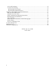
Air-Cooled Condenser............................................................................................................... 24 E-Coated Coil Cleaning ............................................................................................................ 24 Recommended Coil Cleaner .................................................................................................. 25 Recommended Chloride Remover ......................................................................................
Index of Tables and Figures Tables: Table 1 - Condenser Flooding....................................................................................................... 18 Table 2 - Acceptable Refrigeration Circuit Values....................................................................... 21 Table 3 - R-410A Refrigerant Temperature-Pressure Chart ......................................................... 22 Figures: Figure 1 - Pressure Relief Valve ..........................................................
Safety Attention should be paid to the following statements: NOTE - Notes are intended to clarify the unit installation, operation and maintenance. CAUTION - Caution statements are given to prevent actions that may result in equipment damage, property damage, or personal injury. WARNING - Warning statements are given to prevent actions that could result in equipment damage, property damage, personal injury or death.
WARNING VARIABLE FREQUENCY DRIVES Do not leave VFDs unattended in hand mode or manual bypass. Damage to personnel or equipment can occur if left unattended. When in hand mode or manual bypass mode VFDs will not respond to controls or alarms. CAUTION PVC (Polyvinyl Chloride) and CPVC (Chlorinated Polyvinyl Chloride) are vulnerable to attack by certain chemicals.
LC Base Model Description Model Number LC Series and Generation - 038 Unit Size BASE MODEL SERIES AND GENERATION LC UNIT SIZE 005 = 5 Nominal Tons 006 = 6 Nominal Tons 007 = 7 Nominal Tons 008 = 8 Nominal Tons 012 = 12 Nominal Tons 015 = 15 Nominal Tons 019 = 19 Nominal Tons 021 = 21 Nominal Tons 026 = 26 Nominal Tons 027 = 27 Nominal Tons 029 = 29 Nominal Tons 038 = 38 Nominal Tons 047 = 47 Nominal Tons 054 = 54 Nominal Tons VOLTAGE 1 = 230V/1Φ/60Hz 2 = 230V/3Φ/60Hz 3 = 460V/3Φ/60Hz 4 = 575V/3Φ/60Hz 8
LC Features Description Feature Number : B G J G 1A 1B 1C 1D FEATURE 1: BUILDING PUMPING 1A: PUMP OPTIONS 0 = Standard, No Building Pump B = Primary Pumping System 1B: PUMP CONFIGURATION 0 = Standard, No Building Pump A = 1 Pump - Std Eff, 1170 RPM C = dualArm Pump - Std Eff, 1170 RPM D = 1 Pump - Prem Eff, 1170 RPM F = dualArm Pump - Prem Eff, 1170 RPM G = 1 Pump w/ VFD - 1170 RPM J = dualArm Pump w/ 2 VFDs - 1170 RPM K = 1 Pump - Std Eff, 1760 RPM M = dualArm Pump - Std Eff, 1760 RPM N = 1 Pump
LC Features Description Feature Number F B 3 4 - 0 0 0 5A 5B 5C - FEATURE 3: CHILLER ACCESSORIES 0 = Heat Trace and Insulation on Water Evaporator A = Heat Trace and Insulation on Glycol Evaporator D = Heat Trace and Insulation on Water Evaporator with Air Scoop E = Heat Trace and Insulation on Glycol Evaporator with Air Scoop F = Heat Trace and Insulation on Water Evaporator with Air Scoop, Thermometers, and Differential Pressure Gauge H = Heat Trace and Insulation on Glycol Evaporator with Ai
LC Features Description Feature Number B 0 12 13 - 0 0 14A 14B - 0 0 0 A 0 0 0 0 B 15 16 17 18 19 20 21 22 23 FEATURE 12: CONTROLS 0 = Standard B = Phase and Brown Out Protection FEATURE 13: SPECIAL CONTROLS FEATURE 18: WARRANTY 0 = Standard A = Second to Fifth Year Extended Compressor Warranty 0 = Standard MCS Magnum Controller A = Standard MCS Magnum with Modem B = Standard MCS Magnum with LonTalk Connection C = Standard MCS Magnum with Diagnostics D = Standard MCS Magnum
General Description LC Series air-cooled condenser chillers are complete self-contained liquid chilling units. They are factory assembled, wired, charged and run-tested. Primary pumping package is available as an optional feature. WARNING Improper installation, adjustment, alteration, service or maintenance can cause property damage, personal injury or loss of life. Installation and service must be performed by a trained, qualified installer.
Never cut off the main power supply to the unit, except for complete shutdown. When power is cut off from the unit, any compressors using crankcase heaters cannot prevent refrigerant migration. This means the compressor will cool down, and liquid refrigerant may accumulate in the compressor. Since the compressor is designed to pump refrigerant gas, damage may occur when power is restored. CAUTION Rotation must be checked on all MOTORS AND COMPRESSORS of three phase units.
Primary Pumping Package Primary pumping uses a single pump to move water (or glycol) through the evaporator and back to the building. This pumping package provides the necessary flow of water to the system. The pump is activated whenever the chiller is given a run signal. Water enters the unit through the return water piping, and then travels through an air scoop to remove any air that is entrapped in the water. Following this, the water flows through a suction guide with strainer.
Dual Pumps When redundant pumping is required, a factory installed dualArm pump can be ordered on units 15 tons and larger. A dualArm pump is a pump with two independent motors and pumps in a single casing. This pump has a swing split-flapper valve in the discharge port to prevent liquid recirculation when only one pump is operating. Isolation valves in the casing allow one pump to be isolated and removed for service while the other pump is still operating.
LC Series chillers have factory installed louvered sheet metal condenser coil guards. The placement relative to the building air intakes and other structures must be carefully selected. Airflow to and from the chiller must not be restricted to prevent a decrease in performance and efficiency. The installation position must provide at least 3 feet of side clearance for proper airflow to the condenser coils.
The AAON low ambient (condenser floodback) system is used to operate a refrigerant system below 25°F outside air temperature. As the ambient temperature drops, the condenser becomes more effective therefore lowering the head pressure. The low ambient system maintains normal head pressure during periods of low ambient by restricting liquid flow from the condenser to the receiver, and at the same time bypassing hot gas around the condenser to the inlet of the receiver.
Condenser Flooding In order to maintain head pressure in the refrigeration system, liquid refrigerant is kept in the condenser to reduce condenser surface. The following chart shows the percentage that a condenser must be flooded in order to function properly at the given ambient temperature.
Startup (See back of the manual for startup form.) WARNING Electric shock hazard. Shut off all electrical power to the unit to avoid shock hazard or injury from rotating parts. WARNING Improper installation, adjustment, alteration, service or maintenance can cause property damage, personal injury or loss of life. Installation and service must be performed by a trained, qualified installer. Before startup of the chiller make sure that the following items have been checked. 1.
Maintenance General Qualified technicians must perform routine service checks and maintenance. This includes reading and recording the condensing and suction pressures and checking for normal sub-cooling and superheat. Compressors The scroll compressors are fully hermetic and require no maintenance except keeping the shell clean. Refrigerant Filter Driers Each refrigerant circuit contains a filter drier.
Compare calculated sub-cooling to the table below for the appropriate unit type and options. Checking Evaporator Superheat Measure the temperature of the suction line close to the compressor. Read gauge pressure at the suction line close to the compressor. Convert the pressure obtained to a saturated temperature using the appropriate refrigerant temperature-pressure chart. Subtract the saturated temperature from the measured suction line temperature to determine the evaporator superheat.
The system is undercharged if the superheat is too high and the sub-cooling is too low. If the sub-cooling is correct and the superheat is too high, the TXV may need adjustment to correct the superheat. Correct an undercharged system by adding refrigerant to the system to reduce superheat and raise sub-cooling. Table 3 - R-410A Refrigerant Temperature-Pressure Chart °F 20 21 22 23 24 25 26 27 28 29 30 31 32 33 34 35 36 37 38 39 40 41 42 43 44 45 46 22 PSIG 78.3 80.0 81.8 83.6 85.4 87.2 89.1 91.0 92.
Lubrication All original motors and bearings are furnished with an original factory charge of lubrication. Certain applications require bearings be re-lubricated periodically. The schedule will vary depending on operating duty, temperature variations, or severe atmospheric conditions. Bearings should be re-lubricated at normal operating temperatures, but not when running. Rotate the fan shaft by hand and add only enough grease to purge the seals. DO NOT OVERLUBRICATE.
Maintenance Recommendations Pump/Fan Motor Maintenance Cleaning - Remove oil, dust, water, and chemicals from exterior of motor and pump. Keep motor air inlet and outlet open. Blow out interior of open motors with clean compressed air at low pressure. Labeled Motors - It is imperative for repair of a motor with Underwriters’ Laboratories label that original clearances be held; that all plugs, screws, other hardware be fastened securely, and that parts replacements be exact duplicates or approved equals.
Surface loaded fibers or dirt should be removed prior to water rinse to prevent restriction of airflow. If unable to back wash the side of the coil opposite of the coils entering air side, then surface loaded fibers or dirt should be removed with a vacuum cleaner. If a vacuum cleaner is not available, a soft non-metallic bristle brush may be used. In either case, the tool should be applied in the direction of the fins.
be removed with the approved cleaning agent. Remove Barrier - Soluble salts adhere to the substrate. For the effective use of this product, the product must be in contact with the salts. These salts may be beneath any soils, grease or dirt; therefore, these barriers must be removed prior to application of this product. Apply CHLOR*RID DTS - Apply directly onto the substrate. Sufficient product must be applied uniformly across the substrate to thoroughly wet out surface, with no areas missed.
Appendix - Water Piping Component Information Water Pressure Relief Valve Automatic Air Vent Valves Overview ASME Rated, Design Certified and Listed by C.S.A. Automatic Air Vent Valves provide air venting for hot or cold water distribution systems. These vents purge air that may be in the water system. Used for protection against excessive pressure on domestic storage tanks or tankless water heaters, the pressure relief valve has no temperature relieving element.
Dimensions & Weights Product Number Size A B C D 431 1” 6” 4” 2-1/2” ** 432 1-1/4” 6” 4” 2-1/2” ** 433 1-1/2” 8” 6” 4” 3/4” NPT 434 2” 8” 6” 4” 3/4” NPT 435 2-1/2” 10” 8” 5-1/2” 1” NPT 436 3” 10” 8” 5-1/2” 1-1/4” NPT 437* 4” 16-5/16” 11-5/8” 7-1/8” 1-1/2” NPT *This size has 125 lb. flanged ends. **No conventional plain steel expansion tank tapping.
may be experienced, steps should be taken to minimize contact or warn operators/users that normal operating conditions will be exceeded. In certain cases where the temperature of the pumped liquid exceeds the above stated temperature levels, pump casing temperatures may exceed 100°C/212°F and not withstanding pump insulation techniques appropriate measures must be taken to minimize risk for operating personnel.
Pump Piping - General CAUTION Piping may carry high temperature fluid. CAUTION The pump must be fully primed on start up. Fill the pump casing with liquid and rotate the shaft by hand to remove any air trapped in the impeller. On split coupled units, any air trapped in the casing as the system is filled must be removed by the manual air vent in the seal flush line. Close-coupled units are fitted with seal flush/vent lines piped to the pump suction area.
discharge gauge reading. Convert the result into the units of the pump head as stated on the pump nameplate and compare the values. Should the actual pump operating head be significantly less than the nameplate head value it is typically permissible to throttle the discharge isolation valve until the actual operating head is equal to the nameplate value. Any noise or vibration usually disappears.
coupled pumps and is flushed and vented to the suction on close coupled pumps. The split-coupled pump is flushed from the pump discharge because the mechanical seal chamber is isolated from the liquid in the pump by a throttle bushing. Because the seal chamber is isolated, seal environmental controls such as filters and separators, when installed in the split-coupled flush line are very effective, as only the seal chamber needs cleansing, and will prolong seal life in HVAC systems.
Noise Levels Estimated Pumping Unit Sound Power Level, (Decibels), A-Weighted, at 1 m (3 ft.) from unit. Vibration Levels Vertical In-Line pumps are designed to meet vibration levels set by Hydraulic Institute Standard HI Pump Vibration 9.6.4.
Procedure for Starting the Pump after Servicing: 1. Ensure serviced pump is fully reassembled including all seal flush lines and drain plugs. 2. Fill the dry casing with system fluid by opening the seal flush line interconnecting valve and the air vent fitting. 3. Allow the pressure to equalize in the two casings, if necessary, by opening seal flush line interconnected valve. 4. Unlock the discharge valve as per instructions below. 5. Unlock the suction valve as per instructions below.
Unlocking: 1. Open the interconnecting valve on the seal flush line to pressurize the serviced pump and vent air through bleeder valve on series 4302. Close these valves once the pressure is equalized and air removed. 2. Loosen set screw (11) and lower locking handle (3) to the horizontal position, secure with set screw (11). 3. Rotate valve to center position so that the center pin of the locking arm (4) locates in the recess on the locking handle (3). 4.
cause arm to rotate quickly with force when unlocked. 3. Rotate valve to center position so that the center pin of the locking arm (4) is located in the recess on the locking handle (3). 36 4. Loosen set screw (11) and raise locking arm (3) to the vertical position, locking the center pin in the locking arm recess, secure with set screw.
Suction Guides Introduction Suction guides are designed for bolting directly onto the suction flange of horizontal or vertical shaft centrifugal pumps. Operating Limits The suction guide is designed to be a fourfunction fitting. Each Suction Guide is a 90º elbow, a Pipe Strainer and a Flow Stabilizer. It may also be used as a Reducing Elbow, should the suction piping be larger than the pump inlet.
Replace the permanent strainer into the fitting body, once the temporary strainer is removed. Replace the cover into the body. Ensuring that the strainer is properly seated, tighten the cover bolts diagonally, evenly and firmly. Flo-Trex Combination Valve Introduction The Flo-Trex combination valves are designed for installation on the discharge side of centrifugal pumps, and incorporate three functions in one valve: 1. Drip-tight shut-off valve 2. Spring closure design, Non-slam check valve 3.
Field Conversion (Straight to Angle Pattern Valve) 1. Open valve at least one complete turn. 2. Remove the body bolts from valve body using Allen Key 4. Position the adjoining flange or the pipe to the Armgrip flange adapter and install the remaining bolts. The two locking bolts should be tightened first in order to position the flange correctly. Note: Care should be taken to ensure that the gasket is not pinched or bent between flanges. 5.
The quarter turn graduations on the sleeve, with the scribed line on the stem provide an approximate flow measurement. Step 5. Locate the differential pressure determined for the valve in the throttled position on the Flo-Trex Performance Curve. Determine the flow rate for the given valve size at this differential pressure. Note: The valve is shipped in closed position. The indicator on the plastic sleeve is aligned with the vertical scribed line on the stem. Step 2.
From the flow characteristic curve, a 4 inch valve at 50% open represents 34% of maximum flow. The approximate flow of a 4 inch valve with a 5.4 ft pressure drop when 50% throttled is: (400 x 34) (25.2 x 34) =136 US gpm; 100 100 =8.57 L/s open and will not turn any further. Torque to a maximum of 45 ft-lbs. This will ensure good metal to metal contact and minimal leakage. Step 3. The valve bonnet may now be removed.
Pressure-Temperature Limits: Flo-Trex Cross Section 1. Body Main 2. Eye Bolt 3. Shaft 4. Spring 5. Spacer 6. Disc 7. Seat 8. O ring body 9. Body Suction 10. Capscrew 12.
LC Series Startup Form Job Name:_______________________________________________ Date:______________ Address:______________________________________________________________________ ______________________________________________________________________________ Model Number:_________________________________________________________________ Serial Number:_____________________________________________ Tag:_______________ Startup Contractor:______________________________________________________________ Address:_
Water/Glycol System 1. Has the entire system been flushed and pressure checked? Yes No 2. Have isolation valves to the chiller been installed? Yes No 3. Has the entire system been filled with fluid? Yes No 4. Has air been bled from the heat exchangers and piping? Yes No 5. Is there a minimum load of 25% of the design load? Yes No 6. Has the water piping been insulated? Yes No 7. Is the glycol the proper type and concentration (N/A if water)? Yes No 8.
Refrigeration System 1 - Cooling Mode Saturated Pressure Temperature Discharge Suction Liquid Line Temperature Refrigeration System 2 - Cooling Mode Saturated Pressure Temperature Discharge Suction Liquid Line Temperature Sub-cooling Superheat N/A N/A N/A Sub-cooling Superheat N/A N/A N/A N/A N/A Condenser Fans Alignment Number Check Rotation hp L1 Nameplate Amps________ L2 L3 1 2 3 4 5 6 Pumping Package hp L1 L2 L3 Flow (gpm) Chiller Pump #1 Chiller Pump #2 47
Maintenance Log This log must be kept with the unit. It is the responsibility of the owner and/or maintenance/service contractor to document any service, repair or adjustments. AAON Service and Warranty Departments are available to advise and provide phone help for proper operation and replacement parts. The responsibility for proper start-up, maintenance and servicing of the equipment falls to the owner and qualified licensed technician. Entry Date 48 Action Taken Name/Tel.
Literature Change History June 2010 Revision of the IOM adding PVC and CPVC piping Caution. April 2011 Revision of the IOM correcting the networking capabilities of the MCS Controller in Feature 13. April 2012 Revision of the IOM adding the refrigerant charging instructions, the electronic startup form, the index of tables and figures, and updating the table of contents.
AAON 2425 South Yukon Ave. Tulsa, OK 74107-2728 Phone: 918-583-2266 Fax: 918-583-6094 www.aaon.com LC Series Installation, Operation & Maintenance R75390 · Rev. B · 120509 (ACP 30091) It is the intent of AAON to provide accurate and current product information. However, in the interest of product improvement, AAON reserves the right to change pricing, specifications, and/or design of its product without notice, obligation, or liability. Copyright © AAON, all rights reserved throughout the world.