front_cover.qxd 10/26/56 5:13 AM Page 2 PH30.
table of contents introduction about this manual features of your PowerPlate™ warning and tips mounting locations system planning system configurations amplifier and crossover controls installation controls and connections signal sources internal signal routing multi-cross™ crossover and configurations constant bass control AC502 operation tuning troubleshooting specifications warranty information 1 2 2 3 3 4 5-9 10-11 12 12-13 14 15 16 17 17 17-18 19-20 21 22 introduction Although it may be hard to remem
about this manual To get the most from your a/d/s/ PowerPlate™, we recommend that you have the installation performed by your qualified authorized a/d/s/ dealer. If this unit is installed by your dealer, we will extend the warranty to two years instead of the standard one-year. However, if you feel that you have the necessary skills and prefer to perform the installation yourself, this manual will guide you through the process of installation and set-up.
warnings and tips Always disconnect the battery ground wire before doing any work on your vehicle. Reconnect the cable only after the installation is complete and the wiring has been checked to make sure that there are no problems. If your radio features a code type security system, be sure you know the code before disconnecting the battery! Your a/d/s/ PowerPlate™ should be installed in 12V negative ground vehicles only.
system planning Proper system planning is the best way to maximize your PowerPlate’s™ performance. By planning your installation carefully you can avoid situations where the performance or the reliability of your system is compromised. Your authorized a/d/s/ dealer has been trained to maximize your system’s sonic potential. Your a/d/s/ dealer is a valuable resource in helping you with your system design and installation.
system configurations All a/d/s/ PowerPlates™ provide extensive features, which make a variety of system configurations possible. It is not feasible to cover all of the possibilities within the few pages of this manual. There are a few system configurations, however, which are extremely popular when used alone or as a "building block" of a larger more elaborate system. Please review systems 1 through 6 described below for suggestions on how to configure the most popular combinations.
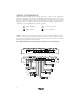
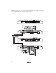
System 2 - PH30.2 used in 5-channel mode with the AC502 providing level control for bridged channels 5 and 6. 1 and 2 are high-passed for front speaker and channels 3 and 4 are high-passed for rear speakers. Although shown as a 4-channel input, the source unit can be either 2 or 4-channel depending on the setting of the 2/4 channel switch. 70A front left satellite front right satellite rear left satellite subwoofer rear right satellite System 3 - PH30.
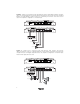
System 4 - PH30.2 used in 4-channel mode with high-pass tweeters and bandpass midrange. Channels 1and 2 are configured high-pass for the main tweeters and channels 3 and 4, and 5 and 6 are configured bandpass for main midrange. Channels 4 and 6 are controlled by the 3/4 level control and crossover section. The amplifier is configured for a 2-channel input. 70A left tweeter right tweeter left midrange right midrange System 5 - PH30.
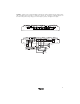
System 6 - PH30.2 used in 3-channel bridged mode with two channels dedicated for the main speakers and one bridged channel pair used for a subwoofer. Channels 1/2, and 3/4 are configured high-pass for the main front speakers using a single pair of RCA inputs to produce a bridged mono output.
System 7 - Two PH30.2’s are used. The first PH30.2 is configured the same as system 4 and the second PH30.2 is configured similar to system 5. The first amplifier drives the front midrange and tweeters and the second amplifier drives the rear speakers and the subwoofer.
10
11 2ch/4ch input switch- Leave this switch OUT if you are using 4 channels of input. Push the switch IN if you have only 2 channels of input to send input 1 and 2 to channels 3 and 4, respectively. (see page 15) 5/6 source- This switch selects the source for channel 5 and 6. Select the input source as input RCA 1 and 2, the summed signals from RCA inputs 1and 3 and 2 and 4, or as RCA inputs 5 and 6.
installation 1. Disconnect the battery ground cable. Reconnect the ground cable only after the installation is complete and the wiring has been checked to make sure that there are no problems. If your radio features a code type security system, be sure you know the code before disconnecting the battery! 2. Run a minimum AWG #8 power wire directly from the battery to the PowerPlate™ mounting location.
70A Connect to 12V turn-on lead from source unit fuse Connect to chassis of vehicle Connect to chassis of vehicle 70 Amp fuse less than 18" from battery Factory chassis ground speaker connections for stereo configurations Minimum recommended impedance is 2 stereo. Speaker terminals accept up to AWG #12 speaker wire. 70A speaker connections for bridged configurations Minimum recommended impedance is 4 when bridged to subwoofers and 4 when bridged to full range speakers.
signal sources Due to the wide input level adjustment range, all a/d/s/ PowerPlates™ can be driven with either a conventional preamplifier drive signal or the amplifier signal from a powered source unit. This makes the PowerPlate™ perfect for upgrading an OEM (Original Equipment Manufacturer) stereo system while retaining the factory installed radio. Because of the high impedance of the a/d/s/ input stage, the factory radio drives an easy load.
internal signal routing 2-channel/4-channel input switch - routes RCA input from channels 1/2 to channels 3/4. When the switch is engaged, channel 1 input is routed to both amplifier channels 1 and 3 with input channel 2 routed to amplifier channels 2 and 4. Switch in the engaged position. When the switch is disengaged, channels 1, 2, 3, and 4 receive signal individually from their respective inputs. Switch in the disengaged position.
multi-cross™ crossover configuration xover control 1/2- The crossover selection for channels 1 & 2 has three options: When the switch is in the left position, the crossover section of the amplifier is bypassed. Channels 1 & 2 output is full range. When the switch is in the center position, channels 1 & 2 are filtered through a 12dB per octave high-pass crossover that is infinitely variable from 45Hz to 5,000Hz.
Constant Bass circuit To mix sub-bass information into channels 1/2 and 3/4, select a lowpass crossover point, and use the level controls to set the level of subbass signal sent to channels 1/2 and 3/4. using the AC502 (optional) The AC502 remote level control, available as an accessory from your a/d/s/ dealer, may be used with your PowerPlate™ to remotely adjust the level of channels 5/6, OR to remotely adjust the constant bass level.
adjusting input sensitivity The input sensitivity setting is important to ensure proper performance, low noise levels, and maximum system reliability. As a general rule, components at the "front end" of the system should be set as high as possible with the input sensitivity of the amplifier set as low as possible while still providing adequate volume levels. Using a high signal level from the source and a low input sensitivity setting on the amplifier will keep the background noise levels of the system low.
troubleshooting symptom possible cause action to take no output low or no remote turn-on input check remote turn-on voltage output at amplifier and correct as needed fuse blown check power wire integrity and reversed polarity, repair as needed and replace fuse power wires not connected check power wire and ground connections and repair or replace as needed audio input not connected or no output from source check input connections and signal integrity, repair or replace as needed speaker wires no
symptom possible cause action to take distorted output (cont’d) speakers are blown check system with known working speakers and repair or replace as needed poor bass response speakers wired with wrong polarity causing cancellation at low frequencies check speaker polarity and repair as needed crossover set incorrectly reset crossovers referring to the multi-cross™ crossover configuration section of this manual for detailed instructions impedance load to amplifier too low check speaker impedance
specifications amplifier section PH 30.2 power output 4 (watts)1 6 channel 6 x 75 3 channel 3 x 250 power output 2 (watts)2 fuse type dimensions distortion all channels driven 6 x 112.5 70 A maxi 13" x 19 7/8" x 2" <0.
warranty information LIMITED TWO YEAR CONSUMER WARRANTY Directed Electronics, Inc. promises to the original purchaser, to replace this product should it prove to be defective in workmanship or material under normal use, for a period of two years from the date of purchase by the dealer as indicated by the date code marking of the product PROVIDED the product was installed by an authorized Directed dealer.
front_cover.qxd 10/26/56 5:13 AM Page 1 Directed Electronics, Inc.