Technical Data Sheet No.
Aalborg7 is a registered trademark of Aalborg7 Instruments & Controls. NOTE: Aalborg7 reserves the right to change designs and dimensions at its sole discretion at any time without notice. For certified dimensions please contact Aalborg7.
TABLE OF CONTENTS 1. 1.1 1.2 1.3 UNPACKING THE TIO TOTALIZER......................................................1 1 Inspecting Package for External Damage.................................................................. 1 Unpacking the TIO Totalizer..................................................................................... 1 Returning Merchandise for Repair............................................................................. 2. 2 SAFETY INSTRUCTIONS / INTRODUCTION....................
7. 7.1 7.2 TROUBLESHOOTING....................................................................68 Common Conditions...........................................................................................68 Troubleshooting Guide........................................................................................
1. UNPACKING THE TIO TOTALIZER 1.1 Inspect Package for External Damage Your TIO Totalizer-Input/Output Flow Monitor/Controller was carefully packed in a sturdy cardboard carton with anti-static cushioning materials to withstand shipping shock. Upon receipt, inspect the package for possible external damage. In case of external damage to the package, contact the shipping company immediately. 1.
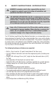
2. SAFETY INSTRUCTIONS / INTRODUCTION AALBORG7 warranties and all other responsibilities by direct or implied are voided if users fail to follow all instructions and procedures described in this manual. LIFE SUPPORT APPLICATIONS: The TIO is not designed for use in life support applications where malfunctioning of the device may cause personal injury.
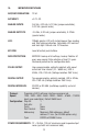
3. SPECIFICATIONS ADC/DAC RESOLUTION: 12 bit. ACCURACY: ±0.1% F.S. ANALOG INPUTS: 0-5 Vdc, 4-20 mA, 5-10 Vdc (jumper-selectable), 0-10 Vdc (special order). ANALOG OUTPUTS: 0-5 Vdc, 4-20 mA (jumper-selectable), 0-10Vdc (special order). LCD: 128x64 graphic LCD with instantaneous Flow reading and Total volume indication. Adjustable LCD contrast and back light. Refresh rate 10 times/sec. KEY-PAD: Local 6 tactical push buttons.
INTERFACE CONNECTORS: Process I/O signals and digital RS-232/RS-485 interface: miniature 9 pin female D-SUB connector. Digital optically-isolated outputs: TERMINAL BLOCK HEADER 4POS 3.5MM male pins, Shrouded (Mated connector: Tyco Electronics P/N: 284510-4). ENVIRONMENT: Installation Level II; Pollution Degree II. ELECTROMAGNETIC COMPATIBILITY: Compliant ref. 89/336/EEC as amended. Emission. Standard: EN 55011:1991, Group 1, Class A. Immunity Standard: EN 55082-1:1992.
4.
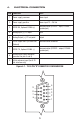
The power supply (PS), process variable (PV) input, set point (SP) control output, and digital communication interface signals are connected to the TIO via miniature 9 pin female D-SUB connector. 4.1 Power Supply Connections The power supply requirements for TIO are: 12 to 26 Vdc, (unipolar power supply). DC Power (+) --------------- pin 2 of the 9 pin "D" connector DC Power (-) --------------- pin 1 of the 9 pin "D" connector CAUTION: Do not apply power voltage above 28Vdc.
Figure 4.2 - TIO Input/Output Configuration Jumpers A B C D 3 6 9 12 15 18 2 5 8 11 14 1 4 7 10 E F G 21 17 20 13 16 19 Table 4.
CAUTION: When connecting the load to the output terminals always check actual jumper J2 configuration. Do not exceed the rated values shown in the specifications (see Table 4.2). Failure to do so might cause damage to this device. Be sure to check if the wiring and the polarity of the power supply and SP signals are correct before turning the power ON. Wiring error may cause damage or faulty operation. Do not connect external voltage source to the SP output terminals. Table 4.
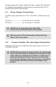
RS-232 Communication Interface Connection: Crossover connection must be established: RS-232 RX (pin 2 on the host PC DB9 connector)------pin 7 of the 9 pin "D" connector (TX-) RS-232 TX (pin 3 on the host PC DB9 connector)------pin 3 of the 9 pin "D" connector (RX+) RS-232 SIGNAL GND (pin 5 on the host PC DB9 connector)------pin 6 of the 9 pin "D" connector RS-485 Communication Interface Connection: The RS485 converter/adapter must be configured for: multidrop, 2 wire, half duplex mode (See Figure 4.3).
10 Figure 4.
When the TIO device is set as the last device on the RS-485 bus segment and 220 Ohm bus termination is required, set the jumper J2G to position 19-20. This will result in connection 220 Ohm resistor between RS-485 (+) and (-) terminals. 4.5 Digital and Pulse Optically-Isolated Outputs Connections TIO is equipped with two programmable digital optically-isolated outputs. Each output can be assigned to any one of many different system events or configured as a pulse output (see Paragraph 5.3.9).
WARNING: Optically-isolated outputs have maximum absolute voltage rating 250 Vdc RMS. Do not exceed maximum allowed limits for voltage. Doing so may cause personal injury or damage to this device.
5. LCD KEY-PAD OPERATION: DATA ENTRY AND CONFIGURATION 5.1 Display Indications Initially, after the power is first turned on, the Banner Screen is shown for 2 seconds, then device firmware and EEPROM data base table revisions on the first line, communication interface type on the second line, baud rate and RS-485 hexadecimal address value on third and fourth lines are shown for another 2 seconds. Subsequently, the actual process information (PI) is displayed.
99.97 A:D T1: litr/min 1589324.5 litr Figure 5.2: TIO Initial PI Screen (Device Function: Flow Meter) 99.97 S: 100.0 litr/min T1: 1589324.5 litr Figure 5.3: TIO Initial PI Screen (Device Function: Flow Controller , NOTE: Actual content of the LCD screen may vary depending on the model and device configuration.
Device Function: Flow Controller Device Function: Flow Meter 51.01 51.01 S: 51.0 litr/min T1: 254898.0 litr A:D litr/min T1: 254898.0 litr 51.01 51.01 KF:D T2: litr/min 436.5 litr KF:D T2: litr/min 436.5 litr 51.01 litr/min A:D KF:D T1: 254898.0 litr T2: 436.5 litr 51.01 litr/min A:D KF:D T1: 254898.0 litr T2: 436.5 litr 51.01 litr/min S 51.0 0.0s CS: 1 0.0 0 M:D L:O S: Off 51.01 litr/min A:D KF:D Events Reg: No Events PO:E U/P: 1.000 litr DO# 1: Pulse Output DO# 2: Disabled Figure 5.
The Set Point value can be adjusted locally using LCD/keypad, remotely via RS232/RS-485 digital interface or can be programmed in advance using user-preset programs of up to sixteen steps (Program Set Point Mode). a) Adjusting Set Point value using local LCD/keypad Current Set Point value is displayed on the second line of the main PI screen, next to the ‘S’ character. 99.97 S: 100.0 litr/min T1: 1589324.5 litr Pressing the ENT button while in the main PI screen will activate Set Point adjustment mode.
, NOTE: Before executing, the program should be entered in the program table (see Paragraph 5.3.16) Current flow rate value Current SP value Current program step Program Mode: E/D 51.01 litr/min S 51.0 0.0s CS: 1 0.0 0 M:D L:Off S: Off Current step time elapsed Program Loop Mode: On/Off Program Run Status: On/Off As shown in the above drawing the Program Run parameter can be toggled “On” or “Off” by pressing the RIGHT and LEFT keypad buttons, while PI screen #4 is active.
Figure 5.5 Pressing the UP or DN button to select the Disabled option and then the ENT button to save settings will disable program protection. If PP password is set to any value more than Zero, the firmware will prompt with “Enter PP Password” (see Figure 5.6). User must enter up to 3 digits program protection code, in order to be able to access password protected menus. Once the correct password is entered, Program Protection is turned off until the unit is powered up again. Figure 5.6 5.
, NOTE: During data entry the input vales are checked for acceptability. If data is not acceptable, it is rejected and a message is generated indicating that the new data has not been accepted. If the menu with tabular entry is selected, the available menu options can be set with the UP and DN buttons and are accepted by pressing the ENT button. 5.3.1 Submenu “Change PP Password” In order to get access to “Change PP Password” menu, Program Protection must be disabled.
20 Ent Device Diagnostic Diagnostic Device Event Reg. Status Event Latch Mask Event Reg. Mask Reset Event Reg. Event Register Menu Analog Input counts Analog Output Value LCD Back Light Set.
Once “Change PP Password” menu is selected, the following screen will appear: Figure 5.8 In order to protect device configuration parameters when changing the PP password, the old PP password must be entered. , NOTE: By default the device is shipped from the factory with Program Protection (PP) password set to Zero (PP Disabled). Once old and new passwords are entered the firmware will prompt with a confirmation message (see Figure 5.9) that the new password has been saved. Figure 5.9 5.3.
Figure 5.10 5.3.3 Submenu “Measuring Units” Use the “Engineering Units and K-Factor Menu” to navigate to “Measuring Units” menu option. This option allows configuration of the flow meter/controller with the desired units of measurement. These are global settings and determine what appears on all process information screens and data log records. Units should be selected to meet your particular metering needs. A total of 47 different volumetric and mass-based engineering units are supported (See Table 5.
The following selections are available: 1 second, 60 seconds (1 minute), 3600 seconds (1 Hour), 86400 seconds (1 Day). The default entry is 60 seconds. If a massbased User-defined Unit is desired, the “UD Unit Use Density” parameter must be set to “YES”. The default entry is “NO” so the Fluid STD Density parameter is not used for flow rate calculation. TABLE 5.
NUMBER FLOW RATE ENGINEERING UNITS TOTALIZER ENGINEERING UNITS DESCRIPTION 28 kg/hr kg Kilograms per hour 29 kg/day kg Kilograms per day 30 lb/sec lb Pounds per second 31 lb/min lb Pounds per minute 32 lb/hr lb Pounds per hour 33 lb/day lb Pounds per day 34 Mton/min Mton Metric Ton per minute 35 Mton/hr Mton Metric Ton per hour 36 Igal/sec Igal Imperial Gal per second 37 Igal/min Igal Imperial Gal per minute 38 Igal/hr Igal Imperial Gal per hour 39 Igal/day
5.3.5 Submenu “K-Factors Settings” Conversion factors relative to Nitrogen are convenient to use when the flow meter/controller mated to the TIO is calibrated for Nitrogen and another gas is required to be measured/controlled. Conversion factors relative to Nitrogen for up to 22 common gases are stored in the TIO (see APPENDIX II). In addition, provision is made for a user-defined conversion factor.
a) Flow Alarm Mode (Tabular entry) This function determines whether the Flow Alarm is Enabled or Disabled. The following selections are available: Enabled or Disabled. The default entry is Disabled. Alarm Mode selections can be set with the UP and DN buttons and are accepted by pressing ENT button. b) Low Flow Alarm (Numerical entry) The limit of required Low Flow Alarm value can be entered in increments of 0.1% from 0 - 100%F.S.
, NOTE: For Flow Meter function the value of the High Flow Alarm must be more than the value of the Low Flow Alarm. d) Flow Alarm Action Delay (Numerical entry) The Flow Alarm Action Delay is a time in seconds that the Flow Rate value remains above the High limit or below the Low limit before an Alarm condition is validated. Valid settings are in the range of 0 to 3600 seconds (default value is 0, no delay).
, NOTE: Before enabling the Totalizer, ensure that all Totalizer settings are configured properly. Totalizer Start values must be entered in the currently active Volumetric or Mass flow engineering unit. The Totalizer will not totalize until the Process Flow Rate becomes equal to or more than the Totalizer Start value. Totalizer Event values must be entered in currently active volume or mass based engineering units.
The default entry is Disabled. Totalizer #1 Auto Reset selections can be set with the UP and DN buttons and are accepted by pressing the ENT button. f) Totalizer #1 Auto Reset Delay (Numerical entry) This option may be desirable when the “Totalizer #1 Auto Reset” feature is enabled. Valid settings are in the range of 0 to 3600 seconds (default value is 0, no delay). g) Reset Totalizer #1 (Numerical entry) The Totalizers #1 reading can be reset by selecting the “Reset Totalizer #1” menu option.
, NOTE: Before enabling the Totalizer, ensure that all Totalizer settings are configured properly. Totalizer Start values must be entered in currently active Volumetric or Mass Flow engineering units. The Totalizer will not totalize until the process flow rate becomes equal to or more than the Totalizer Start value. Totalizer Event values must be entered in currently active volume or mass-based engineering units.
e) Totalizer #2 Power On Delay (Numerical entry) Sometimes it is convenient to start the Totalizer only after a specified power-up delay interval. Most of the mass flow meters and controllers require some warm-up time from the power-up event in order to stabilize process variable output and to get accurate reading. “Totalizer #2 Power On Delay” option allows setting a specified time interval which must elapse from the device power-up event before the Totalizer will be activated.
5.3.9 Submenu “Pulse Output” The flow Pulse Output is operates independently from Totalizers and is based on configuration settings (see Figure 5.7) which can provide pulse frequency proportional to instantaneous fluid flow rate. The LCD/keypad and digital communication interface commands are provided to: • • • • , Enable/Disable Pulse Output Start Pulse Output at preset flow rate (0.0 – 100.0 %F.S.
5.3.10 Submenu “Opt. Outputs Settings” Two sets of optically-isolated digital outputs are provided to actuate user-supplied equipment. These are programmable via digital interface or LCD/Keypad such that the outputs can be made to switch when a specified event occurs (e.g. when a Low or High Flow Alarm limit is exceeded, when the Totalizer reaches a specified value), or it may be directly controlled by user. The user can configure each optical output action from 9 different options: • Disabled: No Action.
5.3.11 Submenu “Display Settings” Process Information screens can be configured to be static (manual control) or dynamic (automatic sequencing). In the static mode pressing the UP button allows the user to page through the PI screens in the forward direction. Pressing DN button, pages through the PI screens in the reverse direction. When the last PI screen is reached, the firmware “wraps around” and scrolls to the initial PI screen once again.
In the example shown above, all PI screens are enabled. Each PI screen is assigned to a corresponding bit in the PI Screen Register. In order to change PI Screen mask settings the user should select the desired screen using UP and DN buttons and then press RIGHT button. The asterisk will appear/disappear on the right side of the corresponding screen. The asterisk signifies that the screen is enabled. In order to disable the screen, the corresponding asterisk must be removed.
, NOTE: Based on “Device Function” (device function as flow meter or flow controller) settings, different parameters may be displayed in the Process Information (PI) screen (See Figure 5.4) and different features of the TIO device may be enabled or disabled (set point control only enabled when TIO is configured as flow controller). Also some features (e.g. Flow Alarm) may have different behavior. Be sure the “Device Function” parameter is set according to the actual device being used. 5.3.
, , NOTE: Address 00 is reserved for global addressing. Do not assign, the global address for any device. When command with global address is sent, all devices on the RS-485 bus execute the command but do not reply with an acknowledge message. NOTE: Do not assign the same RS-485 address for two or more devices on the same RS-485 bus. If two or more devices with the same address are connected to the one RS-485 network, a communication collision will take place on the bus and communication errors will occur.
c) Flow Power Up Delay (Numerical entry) Sometimes it is convenient to start the process input signals after the specified power-up delay interval. Most mass flow meters and controllers require some warm-up time from the power-up event in order to stabilize process variable output and get accurate reading. “Flow Power UP Delay” option allows a set specified time interval which must elapse from the device power-up event, before processing of the input signals will be activated.
f) Analog Input Calibration , NOTE: The analog inputs available for the TIO were calibrated at the factory. There is no need to perform analog input calibration unless the CPU IC, input amplifier IC or passive components from the analog input circuitries were replaced. Any alteration of the analog input scaling variables in the EEPROM table will VOID the calibration warranty supplied with instrument.
5.3.15 Submenu “Signal Conditioner” A noise reduction filter algorithm (Running Average or Noise Reduction Filter) is available in the flow meter when pulsating flow or especially noisy signals are encountered. The Flow Linearizer algorithm is also available when flow linearity must be improved. There are three parameters which make up Running Average Filter: • Number of Samples • Time Interval • Error Limit They are described individually below.
d) NRF Error Limit (Numerical Entry) The Error Limit value can be selected between 0.0 and 10.0 % F.S. (for consistency) . The value represents the difference of the signal sample from previous measured value. The Error Limit is configured to reject noise spikes within the flow range while allowing normal variation of the flow signal. The factory default setting 2.0% of full scale optimizes noise rejection in most applications.
, Note: It is recommended to use Aalborg7 supplied calibration and maintenance software for linearization table calibration. This software includes an automated calibration procedure which may radically simplify reading and writing for the EEPROM linearization table. 5.3.16 Submenu “Program Set Point” The Program Set Point Control allows execution of custom, user-preset programs of up to sixteen steps.
PSP Steps Masc: S01 0.0% S02 S03 S04 S05 0.0% 25.0% 25.0% 50.0% 0s [*] 10s 25s 10s 25s [*] [*] [*] [*] In the example shown above, all PSP Steps are enabled. Each PSP Step assigned to a corresponding bit in the PSP Steps Register. In order to change PSP Step mask settings user should select desired Step using UP and DN buttons and then press RIGHT button. The asterisk will appear/ disappear on the right side of the corresponding Step. The asterisk represents that Step is enabled.
The following Diagnostic Events are supported: Table 5.
The following settings are available for “Event Register Menu” (see Figure 5.7): a) Event Register Status (Read Only) Each active Alarm Event will be indicated on the LCD screen. In addidtion the total number of currently active events will be displayed on the first line (header). A typical display without active diagnostic and Alarm Events is shown below. Event Reg. Status: 0 No Active Events A typical display with two active events is shown below. Event Reg.
Events Latch Mask: 0-CPU Temp. High [*] 1-Hight Flow Alm. [ ] 2-Low Flow Alm. [] 3-Range b/w H-L [ ] 4-Tot#1> Limit [] In the example shown above, latch features for all events are disabled, except event #0. In order to change Event Latch mask settings, the user should select the desired event using UP and DN buttons and then press the RIGHT button. The asterisk will appear/disappear on the right side of the corresponding event. The asterisk represents that the latch feature is enabled.
d) Reset Event Register (Tabular entry) The Event Register can be reset by selecting “Reset Event Register” menu option. A typical display with Reset Event Register screen is shown below. Reset Event Reg.: NO YES DO YOU WANT RESET EVENT REG? Once the “YES” option is selected, the Event Register will be reset and the following conformation screen will appear. ********************** Event Reg. Has been reset! Press any key... 5.3.
Analog Output Value: Output Conf: 0-5 Vdc DAC Update: Enabled DAC Counts: 0 c) LCD Back Light Settings (Read Only) This menu selection provides information about LCD back light level, PWM duty cycle and contrast (read only). A typical display with LCD Back Light Settings screen is shown below. LCD Back Light Set: TIM3_CCR1: 12 Duty Cycle: 60% Contrast: 6 d) Pulse Output Queue (Read Only) This menu selection provides information about Pulse output queue.
6. INSTALLATION 6.1 General Directions • Mounting, electrical installations, parameters configuration, start up, and maintenance of this instrument may only be performed by trained personnel. Personnel must read and understand this operating manual before performing any installation or configuration steps. • The TIO device should only be operated by trained personnel. All instructions in this manual are to be observed.
6.2.1 Connecting TIO to GFM series Flow Meter a) Mounting Use GFM mounting kit (See Table 5.1) to attach TIO to the GFM Flow Meter (see Figure 6.1). Figure 6.1 Mounting TIO to the GFM Flow Meter b) Electrical Connection GFM Flow Meters have three different output interfaces (0-5, 5-10 Vdc, 4-20 mA) which can be used to provide flow input signal to TIO.
51 Figure 6.2 Connecting TIO to the GFM using 0-5 Vdc output from DB9 connector.
52 Figure 6.3 Connecting TIO to the GFM using 5-10 Vdc output from RJ11 connector.
53 Figure 6.4 Connecting TIO to the GFM using 4-20 mA output from DB9 connector.
Based on interface being used, Optional Cables Kit Assemblies are available for order. See Table 6.1 for optional GFM cables kit assemblies. TABLE 6.
TABLE 6.
6.2.2 Connecting TIO to GFC series flow controller a) Mounting Use GFC Mounting Kit (See Table 6.3) to attach TIO to the GFC flow controller (see Figure 5.5). Figure 6.5 Mounting TIO to the GFC Flow Controller b) Electrical Connection GFC flow controllers have two output interfaces: 0-5 Vdc and 4-20 mA which can be used to provide flow input signal to TIO. They also support two analog input signals: 0-5Vdc and 4-20 mA (jumper-selectable on the GFC PC board).
58 Figure 6.6 Connecting TIO to the GFC Using 0-5Vdc Input / Output from DB15 Connector.
59 Figure 6.7 Connecting TIO to the GFC Using 4-20mA Input / Output from DB15 Connector.
Based on interface being used and power supply option, optional Cables Kit Assemblies are available for order. See Table 6.3 for optional GFC Cables Kit Assemblies. TABLE 6.
Kit Part Number Description TIO Input/Output Communication GFC Power Interface Cable Supply Option Shielded cable with KIT-TCAUSTRALIA plug 240 Vac 240AU-2N to 12 Vdc power supply 0-5 Vdc NO 12 Vdc only Shielded cable with KIT-TC- AUSTRALIA plug 240 Vac 240AU-4C to 24 Vdc power supply, communication branch 0-5 Vdc YES 24 Vdc only Shielded cable with KIT-TCAUSTRALIA plug 240 Vac 240AU-4N to 24 Vdc power supply 0-5 Vdc NO 24 Vdc only Shielded cable with UK plug 240 Vac to 12 Vdc power supply,
c) Input/Output Jumper Configuration , NOTE: Your TIO device input / output jumpers were configured at the factory according to your order. There is no need to change the input / output jumper’s configuration unless different input is being used. Before applying power and process signals make sure the input / output jumpers are installed in the correct position (See Table 6.4). TABLE 6.
d) Parameters configuration The following parameters must be configured: • Device Function (See 5.3.12 Submenu “Device Function”). “Controller” function must be selected. • Full Scale Range (See 5.3.14 Submenu “Device Calibration”). Full Scale Range parameter must be set equal to the GFC full scale flow rate in Litr/min. • Fluid Std. Density (See 5.3.14 Submenu “Device Calibration”). This parameter is required only when mass-based engineering units are selected.
Panel Mounting Figure 6.8 Dimensions for Panel Mounted Installation b) Electrical Connection TIO can be used with any generic flow meter / controller which supports 0-5 Vdc and / or 4-20 mA input / output interfaces. It also can be ordered for 0-10 Vdc input / output interface (special order not supported by generic models). , NOTE: Do not connect TIO input / output circuitry to voltages above 5.5Vdc unless TIO was specifically ordered for 0-10 Vdc input / output interface.
65 Figure 6.
66 Figure 6.
c) Input/Output Jumper Configuration , NOTE: Your TIO device input / output jumpers were configured at the factory according to your order. There is no need to change input / output jumper’s configuration unless different input is being used. Before applying power and process signals, make sure the input /out put jumpers are installed in the correct position (See Table 6.5). TABLE 6.
, NOTE: When TIO is connected to flow meter, output circuitry is not used. Jumpers J2A, J2B, J2C configuration is not applicable in this case and they should not be changed. In order to disable analog output, jumper J2B must be removed. d) Parameters configuration Following parameters must be configured: • Device Function (See 5.3.12 Submenu “Device Function”). If TIO is connected to flow controller, then “Controller” function must be selected.
7.2 NO. Troubleshooting Guide INDICATION LIKELY REASON 1 LCD Display remains Power supply is bad or blank when unit is polarity is reversed. powered up. Status LED is OFF 2 LCD Displays flow reading, but 4-20 mA set point output signal does not change PC board is defective. SOLUTION Measure voltage on pins 2 and 1 of the DB9 interface terminal connector. If voltage is out of specified range, then replace power supply with a new one.
NO. 5 6 INDICATION Erratic Flow rate Reading Totalizer reading is wrong LIKELY REASON Wrong configuration of Check J2 input jumper configuration (see J2 Input/Output Table 6.4) If necessary contact factory for Jumpers additional help. TIO “Full Scale Flow” parameter value (in litr/min) is not equal to the mated device full scale range Check settings for “Full Scale Range (See Paragraph 5.3.14 Submenu “Device Calibration”).
APPENDIX A TIO Totalizer Input/Output Flow Monitor/Controller EEPROM Variables Rev.A001 [08/10/2011] INDEX NAME DATA TYPE NOTES 0 BlankEEPROM[10] char[10] Do not modify.
INDEX NAME DATA TYPE NOTES 34 SetPointPFS float Set Point value in %FS fraction notation [0.0 - 1.
INDEX NAME DATA TYPE NOTES 71 Total1_Volume_BkUp float Totalizer#1 backup volume in %s (saved every 6 minutes) 72 Total1_AutoReset uint Reset Total.
INDEX NAME DATA TYPE NOTES 105 FlowTbl[3]. FlowPFSOut float Flow Linearizer Index 3 PFS Out [0.0 – 1.0] 106 FlowTbl[4]. FlowPFSIn float Flow Linearizer Index 4 PFS In [0.0 – 1.0] 107 FlowTbl[4]. FlowPFSOut float Flow Linearizer Index 4 PFS Out [0.0 – 1.0] 108 FlowTbl[5]. FlowPFSIn float Flow Linearizer Index 5 PFS [0.0 – 1.0] 109 FlowTbl[5]. FlowPFSOut float Flow Linearizer Index 5 PFS Out [0.0 – 1.0] 110 FlowTbl[6]. FlowPFSIn float Flow Linearizer Index 6 PFS In [0.0 – 1.
INDEX NAME DATA TYPE NOTES 142 PSPTbl[5].Time float PSP Table Index 5 Time (sec) 143 PSPTbl[6].PFS float PSP Table Index 6 Set Point PFS (0.0-1.0) 144 PSPTbl[6].Time float PSP Table Index 6 Time (sec) 145 PSPTbl[7].PFS float PSP Table Index 7 Set Point PFS (0.0-1.0) 146 PSPTbl[7].Time float PSP Table Index 7 Time (sec) 147 PSPTbl[8].PFS float PSP Table Index 8 Set Point PFS (0.0-1.0) 148 PSPTbl[8].Time float PSP Table Index 8 Time (sec) 149 PSPTbl[9].
APPENDIX B Internal K-Factors Table INDEX K Factor Relative to N2 ACTUAL GAS Cp [Cal/g] DENSITY [g/I] 1 Argon Ar 1.4573 .1244 1.782 2 Arsine AsH3 0.6735 0.1167 3.478 3 Boron Triflouride BF3 0.5082 0.1778 3.025 4 Bromine Br2 0.8083 0.0539 7.130 5 Acetylene C2H2 0.5829 0.4036 1.162 6 Cyanogen C2N2 0.61 0.2613 3.322 7 Methane CH4 0.7175 0.5328 0.715 8 Chlorine Cl2 0.86 0.114 3.163 9 Carbon Dioxide CO2 .7382 .2016 1.964 10 Carbonyl Fluoride COF2 0.5428 0.
APPENDIX C Totalizer-IO ASCII Commands Set RS232/RS485 Rev. A1 07/18/2011 The standard Totalizer-IO comes with an RS232 interface. The protocol described below allows communication with the unit using either a custom software program or a “dumb” terminal. All values are sent as printable ASCII characters. For RS-232 interface, the start character and two characters of address must be omitted. For the RS485 interface the start character is always ‘!’ and two characters of the address follow.
78 Diagnostic Events Register Read/Reset current status of Diagnostic Events Register See list of the Diagnostic Events below. [0.000001-10000.0] g/litr Read / Set Fluid Density for standard conditions in g/litr 4 3 DE D S Set point value in current EU 2 (Read, Write) With Argument #2 = ‘S’ set point value will be saved in the EEPROM Set Point Density F COMMAND 1 NO.
79 Device Info Read device configuration info: 7 - full scale range (L/min) - device function (M/C) - input settings (V,C) - output settings (V,C) - low flow cut off (%F.S.) - power up delay (sec.) 6 5 Display/Set Diagnostic Events Mask Register See list of the Diagnostic Events below. NO. DESCRIPTION Diagnostic Display/Set Diagnostic Events Latch Mask register Events Latch Mask See list of the Diagnostic Events below.
80 DESCRIPTION NO. Controller Alarm conditions: Flow-SP High Limit = H SP-Flow Low Limit = L Low > SP-Flow < High = N Meter Alarm conditions: Flow ≥ High Limit = H Flow ≤ Low Limit = L Low < Flow < High = N Note: If device function is set to “Meter” the High Alarm value must be more than Low Alarm value. Flow Alarms Sets / reads the parameters of 8 the Flow Alarms.
81 Device Function Optical Outputs COMMAND NAME – – – – – T1 T2 PO DE M No Action (disabled*) Low Flow Alarm High Flow Alarm Range between High & Low Alarms Tot#1 Reading > limit Tot#2 Reading > limit Pulse Output Diagnostic Events Manual On (enabled) M – Flow Meter C – F low Controller Sets / Reads Device Function Device Function: – – – – D AL AH AR Assigns action of the two optical outputs. The optical outputs can be assigned to: DESCRIPTION O COMMAND 10 DF 9 NO.
82 Totalizers COMMAND NAME NO. Totalizer#1 reading is stored in EEPROM (non-volatile) memory. Power cycle will not affect Totalizer#1 reading.Totalizer#2 reading is backed up in EEPROM with 6 minutes interval. Power cycle may affect Totalizer#2 reading. Totalizer#1 cannot be reset if ResetLock (EE index 70) value set to 1. NOTE: Start Totalizer at Flow value must be entered for in %FS (0.0 – 100.0). Limit volume must be entered in currently selected EU.
83 Pulse Output COMMAND NAME NO. COMMAND Pulse active time in ms must be at least twice less than pulse period (1/F). Example: Maximum flow rate: 600 liter/min (600 liter/min = 10 liters per second) If Unit/Pulse is set to 10 liters per pulse, the output will pulse once every second (F=1 Hz). EU must not be time based. It is recommended to set the unit/pulse value equal to the maximum flow in the same units per second. This will limit the pulse to be no faster than one pulse every second.
84 Units of measure COMMAND NAME Igal MilL Mton Bbl – – – – Imperial Gal million liters Ton (metric) Barrels Density Argument: Y – use density N – do not use density For User-defined units: k-Factor value represents conversion value from L/min. Time base argument: S – seconds M – minutes H – hours D – days Note: The units of the Totalizer output are not per unit time. Set units of measure for flow rate and Totalizer reading. DESCRIPTION COMMAND 13 U NO.
85 COMMAND NAME DESCRIPTION NO. COMMAND ARGUMENT 1 No Argument (status) USER (User-defined) Mton/min Mton/hr Igal/sec Igal /min Igal /hr Igal/day MilL/min MilL/hr MilL/day bbl/sec bbl/min bbl/hr bbl/day [>0.0] ARGUMENT 2
86 Calibration Settings K-Factor COMMAND NAME NO. NOTE: must be reset to zero after calibration. Argument 1 = T Hours since last time unit was calibrated. Sets/Reads Calibration related variables. Mode: D – Disabled (K-Factor = 1.0) I – Internal U – User-Defined 15 Read and set K-Factor relative to 14 N2 DESCRIPTION C K COMMAND Z Set Cal. Timer to Zero T Read/Reset Calibration/ Maintenance Timer L Device Low Flow Cut Off in % of full scale CT:Z CT: Example: CT:1024.
87 DESCRIPTION NO. COMMAND Sets/Reads Signal Conditioner 16 SC Signal Conditioner Parameters Settings Argument1 = F: Display/Change NR Filter Parameters: NRF Sample Number [1-32] NRF Time Limit [0-199] NRF Error Limit [0.0-10.0%] COMMAND NAME ARGUMENT 1 E- Enable D- Disable L Device Flow Linearizer F NR Filter Settings: NRF Sample Numb.
88 LCD and Process Screens Settings COMMAND NAME See list of the Process Screens below: 0x01 – Flow/Set Point, Tot#1 0x02 – Flow, Tot#2 0x04 – Flow,Tot#1, Tot#2 Argument 1 = S Process Screens Mask register: 0x00FF – screen mask (8 bits wide). Set bit – Enable Clear bit – Disable Sets/Reads LCD related parameters. DESCRIPTION COMMAND 17 L NO. S Process Screens Mask register LS:0x03 0x00FF – screen mask (8 bits wide).
89 DESCRIPTION Program Set Point Sets/Reads Program Set Point parameters Flow Rate (in current EU) Totalizer #1 (in current EU) Totalizer #2 (in current EU) Flow Alarm Status (D,N,L,H) Diagnostic Events Register Read Process Information Process Information Returns: COMMAND NAME COMMAND 19 PS 18 PI NO. ARGUMENT 1 RESPONSE PSP:,
90 Write EEPROM Memory Read EEPROM Memory COMMAND NAME COMMAND 20 MR NO. 21 MW Writes the specified value to the specified memory location. Use Carefully, Can cause unit to malfunction. (Note: Some addresses are write protected!) Reads the value in the specified memory location. DESCRIPTION No Argument (Ret.
UART ERROR CODES Not Supported Command or Back Door is not enabled. Wrong # of Arguments. Address is Out of Range (MR or MW commands). Wrong # of the characters in the Argument. Attempt to Alter Write Protected Area in the EEPROM. Proper Command or Argument is not found. Wrong value of the Argument. Reserved. Manufacture specific info EE KEY (wrong key or key is disabled).
APPENDIX D Mechanical Drawings 92
APPENDIX E Circuit Layout Diagrams Circuit Layout Top 93
Circuit Layout Bottom Mirror 94
APPENDIX F Warranty Aalborg7 TIO Totalizer Input/Output Flow Monitor/Controller is warranted against parts and workmanship for a period of one year from the date of purchase. It is assumed that equipment selected by the customer is constructed of materials compatible with the environment in which the TIO is being used. Proper selection is the responsibility of the customer.