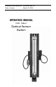
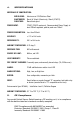
Technical Data Sheet No. TDXXXXM Rev.
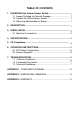
TABLE OF CONTENTS 1. UNPACKING the Optical Sensor Switch....................................... 1 1.1 Inspect Package for External Damage.................................. 1 1.2 Unpack the Optical Sensor Switch........................................ 1 1.3 Returning Merchandise for Repair......................................... 1 2. DESCRIPTION..................................................................................1 3. INSTALLATION..................................................................
Aalborg7 is a registered trademark of Aalborg Instruments & Controls. Aalborg7 reserves the right to make changes to information and specifications in this manual without notice.
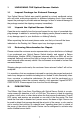
1 UNPACKING THE Optical Sensor Switch 1.1 Inspect Package for External Damage Your Optical Sensor Switch was carefully packed in a sturdy cardboard carton, with anti-static cushioning materials to withstand shipping shock. Upon receipt, inspect the package for possible external damage. In case of external damage to the package contact the shipping company immediately. 1.2 Unpack the Optical Sensor Switch Open the carton carefully from the top and inspect for any sign of concealed shipping damage.
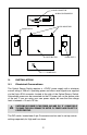
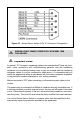
9-PIN D-CONNECTOR ALARM CONFIGURATOR LED INDICATORS PHONE JACK 2 RESET BUTTON PHONE JACK 1 POWER JACK 3. INSTALLATION 3.1 Electrical Connections The Optical Sensor Switch requires a +12VDC power supply with a minimum current rating of 250 mA. Operating power and alarm reset signals are supplied via the 9-pin AD@ connector located at the side of the Optical Sensor Switch. Alternatively power can be connected via the DC power jack on the bottom side of the unit.
Figure 3.1, Optical Sensor Switch 9 Pin “D” Connector Configuration. WARNING: DO NOT CONNECT POWER SUPPLY WITH MORE THAN 15Vdc VOLTAGE. Important notes: In general, “D” Connector numbering patterns are standardized. There are, however, some connectors with nonconforming patterns and the numbering sequence on your mating connector may or may not coincide with the numbering sequence shown in our pin configuration table above.
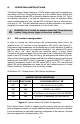
4. SPECIFICATIONS MATERIALS OF CONSTRUCTION: END BLOCKS: ELASTOMERS: FLOW TUBE: POWER INPUT: Aluminum or 316 Stainless Steel. Buna7 & Viton7 (Aluminum), Viton7 (316 SS). Borosilicate glass. 12VDC (15VDC maximum), Recommended Power Supply at least 250mA regulated, peak to peak max 100mV. POWER CONSUMPTION: Less than 200mA. ACCURACY: +/- 2% of full scale. REPEATABILITY: 0.5% of full scale. AMBIENT TEMPERATURE: 0-70 deg. C. RESPONSE TIME: 500 milliseconds. SOURCE OF LIGHT: 650nm, red LED.
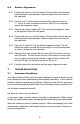
6. OPERATING INSTRUCTIONS The Optical Sensor Switch requires a +12VDC power supply with a minimum current rating of 250 mA. During initial power up of the Optical Sensor Switch with no flow conditions the red LED on the retro reflective sensors will be “On”. This is an indication that power is on and the sensors are ready for operation. When alarm conditions become “true”, the red LED on the top of the retro reflective sensors goes to “Off”.
6.2 Sensor Alignments 6.2.1 Position the sensor on the side panel of the flow tube until the upper small alignment screw becomes visible through the service hole on the side panel. 6.2.2 Using a small 1/16 hex wrench unscrews the alignment screw for 1 – 2 turns in order to release the sensor. Note: Do not completely remove the alignment screw! 6.2.3 Perform the same procedure (6.2.2) for the second alignment screw at the opposite side of the side panel. 6.2.
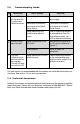
7.2 Troubleshooting Guide NO . INDICATION 1 No red LED light on the top of the Tyne-Eye retro reflective sensors. 2 3 Buzzer or Relay does not work. The retro reflective sensor does not react on passing float (the red LED does not switch to Off). LIKELY REASON SOLUTION Power supply off. Check connection of the power supply. Check cable or connection from sensor to the Optical Sensor Switch. Check cable or connection from sensor to the Optical Sensor Switch.
APPENDIX 1 COMPONENTS DIAGRAM APPENDIX 2 DIMENSIONAL DRAWINGS 2.01 2.20 2.22 1.00 3.
APPENDIX 3 WARRANTY Aalborg7 Optical Sensor Switch is warranted against parts and workmanship for a period of one year from the date of purchase. Calibrations are warranted for up to six months after date of purchase, provided calibration seals have not been tampered with. It is assumed that equipment selected by the customer is constructed of materials compatible with gases used. Proper selection is the responsibility of the customer.