
User Manual


Embedded Controller TKS-G20-LN05 Rev.B
Appendix B DIO B-4
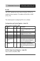
Bit Name R/W PWR Description
7 GP27_PSTS RO VSB3V Read the GPIO27 data on the pin.
6 GP26_PSTS RO VSB3V Read the GPIO26 data on the pin.
5 GP25_PSTS RO VSB3V Read the GPIO25 data on the pin.
4 GP24_PSTS RO VSB3V Read the GPIO24 data on the pin.
3 GP23_PSTS RO VSB3V Read the GPIO23 data on the pin.
2 GP22_PSTS RO VSB3V Read the GPIO22 data on the pin.
1 GP21_PSTS RO VSB3V Read the GPIO21 data on the pin.
0 GP20_PSTS RO VSB3V Read the GPIO20 data on the pin.
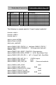
The following is a sample code for “4 input 4 output read/write.”
#include <stdio.h>
#include <stdlib.h>
#include <dos.h>
#define smbase 0xF000
#define Show_Len 0x50
#define dev_addr 0x6E
#define SMBUS_REG_STATUS 0 //defined in SMBUS_STATUS_*
#define SMBUS_REG_COMMAND 2 //Write operation, defined in
SMBUS_CMD_*
#define SMBUS_REG_RESET_POINTER 2 //Read operation
#define SMBUS_REG_DATA_OFFSET 3 //b7:0 = Byte (Word) Offset
#define SMBUS_REG_DID_RW 4 //b7:1 = DeviceID, b0 = Read/Write
#define SMBUS_REG_HST_D0 5 //DATA 0 register
#define SMBUS_CMD_START 0x40
#define SMBUS_CMD_CMD_RW 0x08 //Command read/write
#define SMBUS_DATA_READ 0x01
#define SMBUS_DATA_WRITE 0x00
#define SMBUS_STATUS_BYTE_DONE 0x80
#define SMBUS_STATUS_IN_USE 0x40
#define SMBUS_STATUS_SMBALERT 0x20
#define SMBUS_STATUS_FAILED 0x10