
User Manual


PC/104 Module PFM-CVS Rev. B
Chapter 2 Quick Installation Guide 2-13
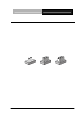
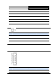
2.12 PC/104 -5V/-12V Voltage Selection (JP11) Res erved
-12V -5V GND
JP11 Function
1 -12V
2 -5V
3 GND
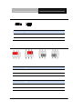
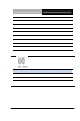
2.13 Backlight Brightness Control Connector (CN2)
Pin Pin Name Signal Type Signal Leve l
1 LVDS Voltage select OUT
2 LVDS Backlight control OUT
3 GND GND
4 GND GND
5 LVDS Backlight Enable OUT
Note: LVDS Voltage can be set to +5V or +12V by JP3.