
Owner manual


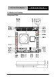

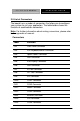
Table Of Contents

PC/104 CPU Module PFM-540I Rev.B
Chapter 2 Quick Installation Guide 2 - 8
2.5 List of Connectors
The board has a number of connectors that allow you to configure
your system to suit your application. The table below shows the
function of each board's connectors:
Note: For further information about mating connectors, please refer
to the appendix of manual.
Connectors
Label Function
CN1 Front Panel Connector
CN2 PS2 Keyboard/Mouse Connector
CN3 Option Power Connector
CN4 USB Connector
CN5 VGA Display Connector
CN6 USB Connector
CN7 PC/104 Connector
CN8 LPT Port Connector
CN9 IDE Connector
CN10 COM1 Connector
CN11 COM3 Connector
CN12 Power Connector
CN13 COM2 Connector
CN14 Ethernet Connector
CN15 LCD Connector
CN16 COM4 Connector