
User Manual


Compact Board PCM-5895
Chapter 2 Quick Installation Guide 2- 8
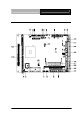
2.5 List of Connectors
The board has a number of connectors that allow you to configure
your system to suit your application. The table below shows the
function of each board's connectors:
Connectors
Label Function
CN1 System FAN
CN2 IrDA
CN4 CAN BUS (Optional)
CN6 USB Port #1 and Port #2
CN7 Front Panel
CN8 USB Port #3 and Port #4
CN9 PC/104 ISA Interface
CN10 ATX Power Socket
CN11 AT Power Socket (Optional)
CN12 IDE Hard Drive
CN13 LAN1 LED
CN14 CRT Display
CN15 Audio Input/Output/CDin/MIC
CN16 Parallel Port
CN17 KB/MS Connector
CN18 Digital I/O
CN19 Serial Port