
User Manual


SubCompact Board GENE-U15B
Chapter 2 Quick Installation Guide 2-16
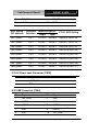
5 PS_ON#
6 +5V_DUAL
2.28 Front Panel Connector (CN29)
Pin Signal Pin Signal
1 Power On Button(-) 2 Power On Button(+)
3 IDE LED(-) 4 IDE LED(+)
5 External Buzzer(-) 6 External Buzzer(+)
7 Power LED(-) 8 Power LED(+)
9 Reset Switch(-) 10 Reset Switch(+)
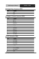
2.29 USB Connector (CN30)
Pin Signal Pin Signal
1 +5V_DUAL 2 GND
3 USBD4- 4 GND
5 USBD4+ 6 USBD5+
7 GND 8 USBD5-
9 GND 10 +5V_DUAL
2.30 Digital I/O Connector (CN31)
Note: The max. rating of Pin 1 ~ Pin 8 is 3.3V@16mA
The max. rating of Pin 9 is 3.3V@0.5A
This connector offers 4-pair of digital I/O functions .
BIOS using the I2C Bus to read/write internal DIO registers and the Serial
Bus address is 0x6E.
Pin Signal Pin Signal
1 DIO_P#1 2 DIO_P#2
3 DIO_P#3 4 DIO_P#4
5 DIO_P#5 6 DIO_P#6