Super Cub R/C Plane LED Night Flying Light Kit Hyperdyne Labs, © 2007-09 http://www.hyperdynelabs.com Congratulations on purchasing the definitive night lighting kit for your R/C Super Cub or other plane! Your kit is hand assembled in the USA, and we appreciate you supporting our products. This kit includes all lights (LEDs), cabling, and assembled processor board to finish your light kit.
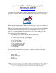
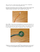
Here is a picture of the assembled processor board w/ X-port cable and LED ribbon cable plugged into the board: NOTE: All LEDs included in this package have positive and negative legs. The longer leg is always the positive side of the LED, and the shorter leg is the negative side of the LED. _ + CONNECTING THE LEDS TO THE MAIN RIBBON CABLE For the semi-assembled kit version, you will need to solder all the LEDs to the ribbon cable. The below instructions go over how to do this with minimal effort.
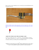
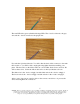
First take the ribbon cable and locate the end with no connector. You want to take your exacto knife and carefully liberate each wire from the cable by cutting carefully in between the cable sheath. This will allow you to pull/rip the wire away from the rest of the sheath. Then splice all the wires using some wire cutters/splicers. The wire is thin so don’t use too much force when splicing. LED hookup diagrams The first LED installed on the ribbon cable is 2 red oval LEDs for the tail.
The next LED to connect is the blue oval LED for the underside. The + lead is soldered to the yellow wire and the – lead is connected to the orange wire on the ribbon cable. The next LED is the yellow cylindrical fuselage LED. The + lead is soldered to the blue wire and the – lead is connected to the green wire. 4 NOTICE: There is no warranty on kits. It is your responsibility to install the board and lights. Kits cannot be returned. This kit can consume a lot of current.
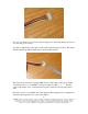
The next LED is the green cylindrical fuselage LED. The + lead is soldered to the gray wire and the – lead is connected to the purple wire. Now take the 4-pin keyed header. You will solder the leads of this connector to the main ribbon cable, so you will be able to unplug the wing lights when disassembling your plane. The next wires on the ribbon cable are colored white, black, brown, and red. We will use these wires. Solder the ribbon cable wires to the keyed header as shown.
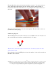
Now you can take the gray extension cable and plug it into the mating header. It is keyed so it will only go in one way. You will see that the gray cable has one wire with a black line going down it. This black mark should line up with the white wire on the main ribbon cable. The next step involves the red wingtip LED clusters. Each wing is made up of 3 LEDs connected in series.
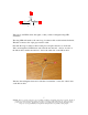
+ _ _ + + _ Take 3 more red LEDs and do this again, so that you have 2 triangular wing LED assemblies. The wing LEDs will attach to the extra long 4-conductor ribbon cable included in the kit. This then connects to the 4-pin gray extension cable. First take the long 4-conductor ribbon cable piece and splice the wires on both ends. Take one triangular red LED cluster and solder the unconnected + lead to one wire on the ribbon cable, and the unconnected – lead to the other wire on the ribbon cable.
Note the polarity of the cables so you can connect them properly to the other end (the colors of the wire above may not be the same as in your kit). Now take the gray 4-pin extension cable and solder the other ends of the long wing ribbon cable to the 4 leads on the end of the gray cable. Solder the – wire from one wing cluster to the gray lead that has a black stripe on the wire. Solder the + wire from that wing cluster to the next lead on the gray cable.
After you are done, you can put some hot glue on the solder points to strengthen the connection. Now you are done with the wing LED hookup! Going back to the main ribbon cable, the next LED to connect is the X-port activity LED. The ribbon wires next on the cable are colored orange then yellow. The + lead is soldered to the yellow wire and the – lead is connected to the orange wire. The last LED to connect is the front white LED cluster. Take the cluster and turn it over.
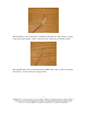
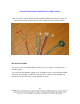
YOU ARE NOW DONE CONNECTING UP THE LIGHTS! Here is a picture of the main ribbon cable with all the LEDs and connectors soldered to their respective ribbon cable wires (in order starting from brown and red wires). KIT INSTALLATION You are now ready to install the lights and the processor board into your Super Cub or other R/C plane. You can run the tail lights through the body. It might be easier to unsolder the tail LEDs and run the wire through a small hole in the tail section.
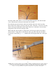
Next install the two fuselage lights. It doesn’t matter which side the yellow or green resides on, it depends on your flying preference. We found it works well with the green on the right side of the fuselage (looking from the front). Punch a hole into the foam and run the LED to the outside of the fuselage. You can use hot glue or foam safe CA glue to hold the LED in place. NOTE: We have found the prime area to place the fuselage LEDs is right under the window decals pointing slightly up towards the wing.
Do the same on the other side for the yellow LED For the blue LED that goes on the underside of the fuselage, we found it easy to place it where the bottom ACT sensor used to reside. We took out these sensors once we mastered piloting the SC. If you still have your sensors installed, you can punch a hole in the foam and run the LED to a spot of your liking. 12 NOTICE: There is no warranty on kits. It is your responsibility to install the board and lights. Kits cannot be returned.
You can use a dab of hot glue to hold the LED in place. NOTE: Point the LED towards the back of the plane and slightly down so you will be able to see it when the plane is flying away from you. The next LED is the X-port activity LED. We placed this where the upper ACT sensor used to be: 13 NOTICE: There is no warranty on kits. It is your responsibility to install the board and lights. Kits cannot be returned. This kit can consume a lot of current.
This LED comes on when you press the X-port button on your transmitter, so you have some feedback that the circuit is working. It will also blink every 5 sec as a heartbeat. For the wing clusters, take some packing tape and run the long ribbon cable on the bottom of the wing. Tape down the ribbon cable as flat as possible. You want the 2 parallel red LEDs to point forwards and backwards on the wing. You want the other LED to bend up and point up to the top of the wing.
Next install the processor board and plug in the LED ribbon cable to the header on the board. The ribbon cable should be facing away from the board if it is plugged in correctly. The processor board fits nicely up against the firewall inside the Cub. You can use Velcro or double-sided tape to secure it onto the foam wall. 15 NOTICE: There is no warranty on kits. It is your responsibility to install the board and lights. Kits cannot be returned. This kit can consume a lot of current.
Next unplug the X-port extension cable already plugged into the stock SC receiver. Now take the X-port cable on the processor board and plug it into your receiver, like shown: The light processor board also has an X-port male “passthrough” connector. Take the Super Cub X-port extension cable that runs down the battery box (this is the cable that is normally plugged into the stock receiver) and plug it into the male header on the processor board.
By default, the lights are off when the board is first powered on. In this mode, the lights will go through a power on verification a couple seconds after the battery is connected. Each light will blink to let you know that it is working ok. Each time you connect a battery to the SC, you will only see this verification step if the “off mode” is selected. Changing light modes using X-port: To change light modes, simply press the X-port button down until you see the X-port activity LED illuminate.
To enter this mode, press and hold the X-port button on your radio for 10 seconds. The plane will respond by blinking all its lights 5 times. Let go of the x-port button. The 5 blinks means the board will no longer accept x-port presses for changing light modes. You can verify this by pressing the x-port button and seeing that the x-port activity LED no longer lights up in response to button presses. Now you can use a drop module, combat module, etc with the light kit.
Next are different views of the HobbyZone™ Super Cub with the installed lights. Bottom: Top: 19 NOTICE: There is no warranty on kits. It is your responsibility to install the board and lights. Kits cannot be returned. This kit can consume a lot of current. Be careful if you plan to use a battery source that is capable of delivering a lot of current. Contact a professional if you need assistance. Hyperdyne Labs assumes no responsibility for the misuse of this kit. Night flying can be dangerous.
Back: Front: 20 NOTICE: There is no warranty on kits. It is your responsibility to install the board and lights. Kits cannot be returned. This kit can consume a lot of current. Be careful if you plan to use a battery source that is capable of delivering a lot of current. Contact a professional if you need assistance. Hyperdyne Labs assumes no responsibility for the misuse of this kit. Night flying can be dangerous.
Right side midline: Left side top: 21 NOTICE: There is no warranty on kits. It is your responsibility to install the board and lights. Kits cannot be returned. This kit can consume a lot of current. Be careful if you plan to use a battery source that is capable of delivering a lot of current. Contact a professional if you need assistance. Hyperdyne Labs assumes no responsibility for the misuse of this kit. Night flying can be dangerous.
NIGHT FLYING TIPS Below are some flying tips to help you discern the orientation of the plane during night flight. We have engineered the lights to allow a skilled pilot to easily visualize the plane at any angle just by observing the visible light pattern. In the below diagrams, we assume the Flight mode lights are enabled.
Light pattern when flying right to left: Level flight or banking away from you Direction of flight Green fuselage indicator Banking towards you Direction of flight Light pattern when flying left to right: Level flight or banking away from you Yellow fuselage indicator Direction of flight 23 NOTICE: There is no warranty on kits. It is your responsibility to install the board and lights. Kits cannot be returned. This kit can consume a lot of current.
Banking towards you Direction of flight With these beginning diagrams, you can see that the orientation of the plane is easily discerned from the light patterns. For your first night flight, memorize which lights are where and start by flying easy level laps around your flying area. This will give you the necessary experience with decoding the plane orientation from just the light patterns. Experienced night pilots can also perform advanced night flying, such as loops, inverted flight, stalls, etc.
entire session, but that means that you cannot easily tell when the receiver battery cutoff will happen. Time your flights appropriately as to not put your plane or people in jeopardy due to low battery cutoffs during night flights! POWER CONSUMPTION The light board uses a variable amount of amperage based on the battery pack you use.