
Installation Guide


25 Page
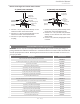
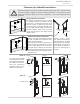
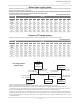
To determine the dimension of a system
Determine the vent diameter (D) and the total vent length based on the number of water
height (H). See the table below.
• Total vent length (L)="H"+"W" +
(Number of Elbows x 5)
• Vent diameter="D"
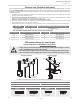
WARNING
• A Non-Return Valve must be installed for each water heater. This prevents
the escape of combuson gas through non-operang appliances.
• For detailed instrucons on the common-venng system, refer to the
instrucons that are packaged with the vent parts or web site.
*Diameters of pipes are in accordance with Centrotherm's specificaons.
**One elbow is equivalent to 5 (1.5 m) linear length, and the maximum number of elbows is 5.
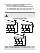
NOTICE
• Regarding the clearances
between the exhaust
terminaon and the
to pp. 26 to 28.
• Insert bird screen in
elbow terminals.
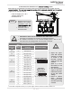
Common-venng system
Vent
Diameter*
(D)
Max.
No. of
water
heaters
Max. Vercal and
Horizontal
(Total) Vent Length** (L)
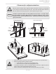
DIP switch sengs
4 in.
(110 mm)
2 25 (7.6 m)
240 Indoor/340 Indoor
OFF
ON
1 2 3 4 5 6 7 8 9 10
No. 6 : ON / No. 7: OFF
540 Indoor
(Upper bank of
DIP switches)
OFF
ON
1 2 3 4 5 6 7 8
No. 3 : ON / No. 4: OFF
5 in.
(125 mm)
2 50 (15.2 m)
3 20 (6.1 m)
6 in.
(160 mm)
2 100 (30.5 m)
3 75 (22.9 m)
4 50 (15.2 m
5 25 (7.6 m)
6 20 (6.1 m)
8 in.
(200 mm)
3 100 (30.5 m)
4 100 (30.5 m)
5 85 (25.9 m)
6 65 (19.8 m)
7 50 (15.2 m)
8 41 (12.5 m)
10 in.
(250 mm)
5 100 (30.5 m)
6 100 (30.5 m)
7 100 (30.5 m)
8 100 . (30.5 m)
"H"
Intake
Exhaust
"D"
Elbow terminal
Elbow terminal
"W"
Non-Return Valve
• Adjust the appro-
priate DIP switches
ledom ot gnidrocca
as shown in the
le table. DO NOT
adjust the other DIP
switches.
(Refer to p. 19 for
the locaon of the
DIP switches.)
• Turn off the power
supply to the water
heater before chang-
ing the DIP switch
sengs.
• Failure to observe
these warnings
could lead to carbon
monoxide poisoning
or death.
WARNING