
Installation Guide


38 Page
Normal Operaon
Owner's Guide
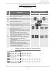
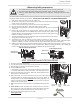
UNIT DRAINING and FILTER CLEANING
1. Close the manual gas shutoff valve.
2. Turn off power to the unit and wait a couple of seconds. Turn on again.
3. Wait 30 seconds, and then turn off power to the unit.
4. Close the inlet water valve.
If the heater is part of an Easy-Link or Multi-Unit System, close the inlet
and outlet water valves to isolate the heater. Then proceed to step 6.
5. Open all hot water taps in the house. When the residual water flow has
ceased, close all hot water taps.
6. Have a bucket or pan to catch the water from the unit’s drain plugs.
If Isolation valves are installed, open the drains to drain the water. If
isolation valves are not installed, unscrew the two drain plugs (large and
small) to drain all the water out of the unit. Do not lose the o-rings that
will be on the two drain plugs.
7. Wait a few minutes to ensure all water has completely drained from the
unit.
8. Clean the filter: Check the water filter located within the cold inlet.
With a tiny brush, clean the water filter of any debris which may have
accumulated and reinsert the filter back into the cold water inlet.
9. Securely screw the drain plugs back into place.
Hand- tighten only.
Inlet
water valve
Drain plug
(Small)
Outlet
water
valve
Drain plug with Filter (Large)
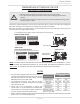
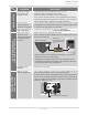
-Measuring inlet gas pressure-
The water heater cannot perform properly without sufficient inlet gas pressure. Below are instructions
on how to check the inlet gas pressure. THIS IS ONLY TO BE DONE BY A LICENSED PROFESSIONAL.
1. Shut off the manual gas valve on the gas supply line.
2. Remove the screw from the pressure port which is located on the gas inlet of the water
heater shown in the diagram on the right.
3. Connect the manometer to the pressure port and zero the manometer.
4. Re-open the manual gas valve. Verify that there are no gas leaks.
5. With all gas burning equipment off, take a reading of the static gas pressure and make
a note of it.
6. Measure gas supply pressure at maximum heater operation: Open hot water faucets
to create maximum flow. Press the MAX button on the computer board. (Refer to the
diagrams below.) Take a reading of the supply dynamic gas pressure with all gas burning
equipment running at maximum rate.
7. The static and dynamic pressures should be within the ranges specified on the heater's
rating plate and the table on page 18.
8. The difference of static to dynamic pressure should not exceed 1.5" W.C. Pressure
drops that exceed 1.5" W.C. can indicate restricted gas flow, undersized gas lines, and/or undersized supply
regulators. (NOTICE: In Canada, the pressure drops cannot exceed those specified in CSA B149.1.)
9. Measure gas supply pressure at minimum heater operation: Reduce water flow so the heater is running at mini-
mal operation. Press the MIN button on the computer board. (Refer to the diagrams below.) Take a supply gas
pressure reading and verify that it is within the specified inlet gas pressure range.
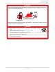
1. Turn off all electric power to the water heater if service is to be performed.
2. Turn the manual gas valve located on the outside of the unit to the off position.
3. Failure to follow these steps could lead to fire or explosion, resulting in personal injury
or death.
WARNING
Pressure
port
110C and 310C Computer board
MAX button
MIN button
510C Computer board
MAX button
MIN button