
Operating Instructions and Installation Instructions


BMS Interface Module
35
6 Status
6.1
6.2
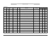
Via the BMS Interface, the state of the water heater and the solar control can be read out
separately. The actual state of the control of the water heater can be found on parameter 7.
When a solar control is present, its state can be viewed on parameter 22.
The numbers that will be read out refer to certain states of the control(s). Some states shall
appear and disappear so quickly that they won’t be visible. This is no problem.
In the table beneath, the reference to the numbers is specified:
Control water heater
Code Description
0 Resetting the control
1 Resetting the control
2 Standby, no active burner cycle
3 Pre purge of the fan / unit
4 Pre purge of the fan / unit
5 Pre purge of the fan / unit
6 Check safety devices
7 Check safety devices
8 Ignition of the gas mixture
9 Ignition of the gas mixture
10 Burning is started, unit is heating up
11 Stop signal for burner cycle
12 Stop signal for burner cycle
13 Post purge of the fan / unit
14 Post purge of the fan / unit
15 Error present
16 Error present
17 Internal check of the control
18 Internal check of the control
19 Internal check of the control
20 Internal check of the control
21 Waiting time between states
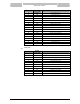
Solar control
Code Description
0 Resetting the solar control
1 Resetting the solar control
2 Standby, no active solar cycle
3 Solar pump started, unit is heating up
4 Error present
5 Waiting time between states