
Operating Instructions and Installation Instructions


BMS Interface Module
25
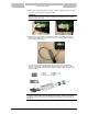
5. Connect the communication cable for Modbus connection, via the pull relief, to the two
connectors on the lower side of the BMS Interface.
ATTENTION:
First connect the twelve way connector containing the ground wire, next the four way
connector can be connected.
6. Afterwards connect the Modbus communication cable to the building management
system in the required way. For this purpose use the connectors which are supplied
together with the BMS Interface.
7. Connect the cable from the building management system to the supplied contra
connector. First lead the cable through the pull relief. This three wire cable (2 wires +
PE) is not supplied with the BMS Interface. Make sure that the wires are connected in
the right sequence.
ATTENTION:
For optimal communication between the BMS Interface and the computer of the building
management system, the cable must be shielded twisted pair with a maximum length of
1200 meters.
1 = brown
Modbus 1 - Tx+
2 = white
Modbus 1 - Tx-
3 = yellow/green
Earth