
Operating Instructions and Installation Instructions


BMS Interface Module
24
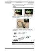
3. In case of a SGE or SGS solar system, connect this communication cable to the blue
two-way connector on the upper right side of the solar control, which is supplied with the
water heater.
4. For Cyclone BFC systems, the communication cable must be connected to the BUS
link connections (X5 and X6) on the far right side of the electrical connection box on top
of the water heater.
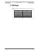
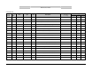
It is possible to select another, longer communication cable for communication between the
BMS Interface and the water heater or solar control. The cable diameter is free to choose.
However, the maximum length of the cable depends on the cable diameter, see the table.
Cable diameter
[mm
2
]
Max. cable length
[m]
0,25 100
0,50 200
0,75 300
1,00 400
1,50 600