
Operating Instructions and Installation Instructions
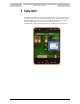


BMS Interface Module
23
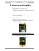
2 Mounting and Installing
2.1
2.2
Together with the BMS Interface, three cables will be supplied:
- Power supply cable
- Communication cable to the (solar) control of the water heater
- Communication cable to connect the BMS Interface to the building management system
(Modbus)
Mounting of the BMS Interface
The BMS Interface should be mounted in the following way:
1. Remove the cover of the BMS Interface
2. Mount the rear side of the BMS Interface to the wall with fitting plugs.
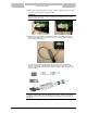
Installation of the BMS Interface
The BMS Interface should be installed in the following way:
1. Connect the power supply cable, via the pull relief, to the three way connector on the
upper right side of the BMS Interface. Connect the other side of the cable to the power
grid by using a double-pole isolator.
ATTENTION:
Do not power up the system until all the electrical connections have been made.
2. Connect the communication cable to the water heater, via the pull relief, to the two way
connector on the lower right side of the BMS Interface.