NL - Instructies voor installatie UK - Installation instructions 0310 168 Innovation has a name.
BMS Interface Module Inhoudsopgave / Table of contents NEDERLANDS 1 Lay-out ................................................................................................................................ 5 2 2.1 2.2 3 Monteren en aansluiten ..................................................................................................... 7 BMS Interface monteren ...................................................................................................... 7 BMS Interface aansluiten .........
BMS Interface Module 4
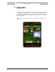
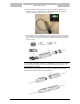
BMS Interface Module 1 Lay-out Deze BMS Interface wordt gebruikt om de ThermoControl-besturing van de Cyclone BFC’s en zonnesystemen, SGE en SGS, te kunnen koppelen aan een gebouwbeheersysteem. De communicatie verloopt via het Modbus protocol en is bedoeld voor uitlezing van gegevens over het aangesloten warmwatertoestel. De BMS Interface is niet voorzien van een eigen display of druktoetsen. De BMS Interface wordt volgens onderstaade uitvoering geleverd in een zwarte kunststof behuizing.
BMS Interface Module 6
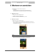
BMS Interface Module 2 Monteren en aansluiten Bij de BMS Interface worden drie kabels meegeleverd: - voedingskabel - communicatiekabel naar de (zonne)besturing van het warmwatertoestel - communicatiekabel voor aansluiting op het gebouwbeheersysteem (Modbus) 2.1 BMS Interface monteren De BMS Interface wordt als volgt gemonteerd: 1. Verwijder het deksel van de BMS Interface. 2. Monteer de achterkant van de BMS Interface op de muur. 2.
BMS Interface Module 3. In het geval van een SGE of SGS zonnesysteem, sluit de communicatiekabel vervolgens aan op de blauwe tweepolige connector aan de rechter bovenzijde van de bij het warmwatertoestel meegeleverde zonnebesturing. 4. Voor een Cyclone BFC wordt de kabel aangesloten op de BUS link aansluitingen (X5 en X6) geheel rechts op de elektrische aansluitbox van het warmwatertoestel.
BMS Interface Module 6. Verbind de Modbus communicatiekabel vervolgens op de gewenste manier met het gebouwbeheersysteem. Gebruik hiervoor de met de BMS Interface meegeleverde connector om de twee kabels aan elkaar te verbinden. 7. Sluit de kabel naar het gebouwbeheersysteem aan op de meegeleverde contrastekker. Voer de kabel eerst door de trekontlaster van de contrastekker. Deze drie aderige kabel (2 aders + aarde) is overigens niet meegeleverd. Let bij het aansluiten van de aders op de juiste volgorde.
BMS Interface Module 10
BMS Interface Module 3 Instellingen Om de BMS Interface te kunnen benaderen vanuit het gebouwbeheersysteem dienen enkele instellingen gedaan te worden.
BMS Interface Module 12
BMS Interface Module 4 Uitlezen De BMS Interface stelt data in Modbus formaat ter beschikking aan het gebouwbeheersysteem. De eindgebruiker dient deze data zelf te ontvangen en verder te verwerken. Hiervoor kan gebruik gemaakt worden van de bijgevoegde parameterlijst. Let hierbij op dat de data nog omgezet dient te worden in het juiste formaat. De hiervoor benodigde conversie staat eveneens in de tabel op volgende pagina’s. LET OP: De hieronder vermeldde parameters zijn allemaal van het type “read only”.
BMS Interface Module 4.1 Parameterlijst Parameter Type register Waarde Type Eenheid Omschrijving 0 03 16 bits direct Adres - 1 03 16 bits direct Temperatuur 2 03 16 bits direct 3 03 4 y = eerste byte x = tweede byte BFC SGS SGE Actuele Modbus adres BMS Interface - Ja Ja Ja °C Temperatuur boven in de tank x/100 Ja Ja Ja Temperatuur °C Temperatuur onder in de tank x/100 Ja Ja Ja 16 bits direct Temperatuur °C Rookgassensor (dummy) x/100 n.v.t. n.v.t. n.v.t.
BMS Interface Module Conversie Toesteltype Parameter Type register Waarde Type Eenheid Omschrijving y = eerste byte x = tweede byte BFC SGS SGE 31 03 16 bits direct Temperatuur °C Retourtemperatuur Q/T-sensor (S4) x/100 n.v.t. Ja Ja 32 03 16 bits direct Temperatuur °C Limiet zonopwarming x/100 n.v.t. Ja Ja 33 03 16 bits direct Bijdrage Watt Zonnebijdrage; actueel - n.v.t. Ja Ja 34 03 16 bits direct Bijdrage MJ Zonnebijdrage; laatste 24u - n.v.t.
BMS Interface Module 16
BMS Interface Module 5 Storingscodes Via de BMS Interface kunnen de interne storingscodes uitgelezen worden. Op parameter 20 staat de actuele storingscode voor de blokkeringen of vergrendelingen. Indien er ook een zonnesysteem is aangesloten kan op parameter 43 de actuele storing van het zonnesysteem uitgelezen worden. De parameters 10 … 14, 15 … 19 en 23 … 27 geven de laatste vijf storingen van respectievelijk de vergrendelingen, blokkeringen en de storingen in het zonnesysteem.
BMS Interface Module 5.
BMS Interface Module 6 Toestel status Via de BMS Interface kan afzonderlijk de status van het toestel en van de zonnebesturing uitgelezen worden. Op parameter 7 staat de actuele status van de besturing van het warmwatertoestel. Indien er ook een zonnesysteem is aangesloten kan op parameter 22 de actuele status van het zonnesysteem uitgelezen worden. De nummers die uitgelezen worden staan voor een bepaalde status van de besturing.
BMS Interface Module 20
BMS Interface Module 1 Lay-out This BMS Interface will be used to connect the ThermoControl of the Cyclone BFC’s and the solar systems SGE and SGS to a building management system. The communication will be handled via a Modbus protocol and is meant for reading the data of the connected water heater. The BMS Interface does not have its own display or push buttons. The BMS Interface will be supplied as pictured below, including the black plastic housing.
BMS Interface Module 22
BMS Interface Module 2 Mounting and Installing Together with the BMS Interface, three cables will be supplied: - Power supply cable - Communication cable to the (solar) control of the water heater - Communication cable to connect the BMS Interface to the building management system (Modbus) 2.1 Mounting of the BMS Interface The BMS Interface should be mounted in the following way: 1. Remove the cover of the BMS Interface 2. Mount the rear side of the BMS Interface to the wall with fitting plugs. 2.
BMS Interface Module 3. In case of a SGE or SGS solar system, connect this communication cable to the blue two-way connector on the upper right side of the solar control, which is supplied with the water heater. 4. For Cyclone BFC systems, the communication cable must be connected to the BUS link connections (X5 and X6) on the far right side of the electrical connection box on top of the water heater.
BMS Interface Module 5. Connect the communication cable for Modbus connection, via the pull relief, to the two connectors on the lower side of the BMS Interface. ATTENTION: First connect the twelve way connector containing the ground wire, next the four way connector can be connected. 6. Afterwards connect the Modbus communication cable to the building management system in the required way. For this purpose use the connectors which are supplied together with the BMS Interface. 7.
BMS Interface Module 8. Finally, place the supplied clip over the connector and use this to lock both connector parts. All the wiring has now been connected properly.
BMS Interface Module 3 Settings To approach the BMS Interface from the building management system, some settings need to be made.
BMS Interface Module 28
BMS Interface Module 4 Data readout The BMS Interface supplies data in a Modbus format to the building management system. The end user will receive this data and needs to process this. The attached parameter list can be used. Pay attention that some data has to be converted into the right format before receiving the expected values. The required conversions are also part of the table given further on. ATTENTION: The parameters mentioned in the table are all of the type “read only”.
BMS Interface Module 4.
BMS Interface Module Parameter Register type Value Type Unit Description 31 03 16 bits direct Temperature °C 32 03 16 bits direct Temperature 33 03 16 bits direct 34 03 35 36 Conversion Unit type y = first byte x = second byte BFC SGS SGE Solar return temperature of the Q/T sensor (S4) x/100 n.a. Yes Yes °C Temperature limit for solar heating x/100 n.a. Yes Yes Contribution Watt Solar contribution; actual - n.a.
BMS Interface Module 32
BMS Interface Module 5 Errors Through the BMS Interface, internal error codes can be viewed. On parameter 20, the actual error code for lock outs and blocking errors are displayed. When a solar system has been connected, parameter 43 gives the actual error code of the solar system. Parameters 10 … 14, 15 … 19 and 23 … 27 show the five most recent errors of respectively the lock outs, blocking errors and solar errors.
BMS Interface Module 5.
BMS Interface Module 6 Status Via the BMS Interface, the state of the water heater and the solar control can be read out separately. The actual state of the control of the water heater can be found on parameter 7. When a solar control is present, its state can be viewed on parameter 22. The numbers that will be read out refer to certain states of the control(s). Some states shall appear and disappear so quickly that they won’t be visible. This is no problem.
BMS Interface Module 0310168 36 1.