
Instruction manual


APPENDIX B: ERROR CODES
Error code Causes Solutions
“C Err 0”
The minimum graduation is other than 1, 2,
5, 10, 20, and 50.
Confirm setting of the minimu
m graduation, CALF-03.
“C Err 1”
Resolution (weighing capacity divided by
minimum graduation) is more than 16000.
Confirm the relations between the weighing capacity
(CALF-04), and minimum division ( CALF-03).
“C Err 2”
The voltage of the zero calibration point is
overloaded in the positive direction.
“C Err 3”
The voltage of the zero calibrated point is
overloaded in the negative direction.
Confirm the rating and connection of the load cell and
see if the loa
d cell is damaged. When the load cell is
connected properly and is not defective, the load cell
output can be corrected by attaching a resistor as
shown below, {Load cell output compensation}.
When it is likely that the load
cell or A/D converter is
defective, use the check mode in {9-1. System
check—“Chc Ad”} to verify the problem.
“C Err 4”
The calibration weight is more than the
weighing capacity.
“C Err 5”
The calibration weight is less than the
minimum division.
Calibrate with proper calibration weights.
“C Err 6”
Sensitivity of the load cell is insufficient.
“C Err 8”
The output voltage of the load cell is too
high with the span capacity loaded
When “C Err 6” or “C Err8” is displayed after CALF-03
(Minimum d
ivision setting) and CALF-04 (Capacity
setting) have been set, try to do the following settings
for solution.
•
•
•
•
Reset CALF-03 (minimum division).
Reset CALF-04 (capacity).
Set CALF-20 (Span input voltage) to “3.200000 “.
Set CALF-21 (Weight against Span input voltage)
to the cap
acity weight.
“C Err 9”
Gravity acceleration rate setting is not
correct. (out of the range).
See {APPENDIX D: Gravity acceleration map} and
set the value again.
“C Err 7”
The voltage of the span calibration point is
negative with respect to the zero point.
Confirm the connection of the load cell.
“ERR St”
Failed to zero when the power was turned
on.
“Err PZr”
Zero was out of the zero valid range when
the power was turned on.
Confirm the connection of the load cell and around
the loa
d cell.
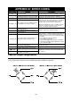
Load cell output compensation
Attach a resistor to a place as shown in the picture below to compensate the load cell output.
Use a resistor with as high resistance and low temperatur
e coefficient as possible.
B-1