
Instruction manual


2-3
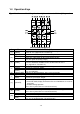
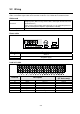
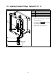
Control signal cable
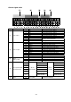
#
Name
Pin #
Name Description
1 IN 1 Control input function—INF-01
2 IN 2 Control input function—INF-02
3 IN 3 Control input function—INF-03
4 IN 4 Control input function—INF-04
5 IN 5 Control input function—INF-05
6 IN 6 Control input function—INF-06
7 COM. 1
8 COM. 2
Common. Connected inside.
[1] Control Input
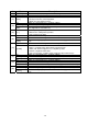
9 F.G. Frame ground
10 OUT 1 Control output function—OUTF-01
11 OUT 2 Control output function—OUTF-02
12 COM. 1 Common for output 1 and 2
13 N.C. No connection
14 OUT 3 Control output function—OUTF-03
15 OUT 4 Control output function—OUTF-04
16 COM. 2 Common for output 3 and 4
17 N.C. No connection
18 OUT 5 Control output function—OUTF-05
19 OUT 6 Control output function—OUTF-06
20 COM. 3 Common for Output 5 and 6
[2] Control output
21 N.C. No connection
22 AN. OUT+ Analog Output (OP-07) High
23 AN. OUT- Analog Output (OP-07) Low
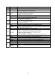
[3]
OP-07
(Analog output)
24 F.G. Frame ground
25 SDA RXD
26 SDB TXD
27 RDA RTS
28 RDB CTS
29 TERM DSR
30
S.G.
(Signal ground)
S.G.
(Signal ground)
[4]
OP-03 (RS-422/485)
OP-04 (RS-232C)
31
OP-03
(RS-422/485)
F.G.
(Frame ground)
OP-04
(RS-232C)
F.G.
(Frame ground)
32
[5]
Standard serial
output
33
C. Loop Out Standard Serial Output