
Instruction manual


2-2
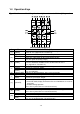
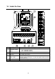
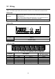
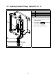
2-2 Wiring
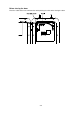
Open the front panel door removing screws on the front panel, and connect a power cable, load cell
cables, and control signal cables to the terminals inside the case. Follow the instructions below.
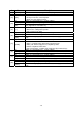
Cable used
Load cell
The use of a 6 wire shielded cable is recommended in order to reduce
weighing error. (When using a 4-wire cable, connect pin # 34 to # 35, and
pin # 36 to # 37.)
If the system requires two or more load cells, use an explosion-protected
type of summing box to input the signal into the indicator.
Control signal cable Use a shielded cable and connect its shield to pin # 40 (Frame ground).
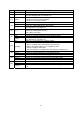
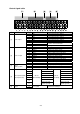
Power cable
Terminal Description
E Ground
N
L
AC power supply
Load cell cable
Terminal Description
Cable color
(ST Series only)
34 EXC+ Excitation + Red
35 SEN+ Sense + Orange
36 SEN- Sense - Black
37 EXC- Excitation - White
38 SIG+ Signal + Green
39 SIG- Signal - Blue
40
F.G.
Frame ground
Yellow