AD-4403-FP Explosion Protected Weighing Indicator ST Series Weighing Indicator for Explosion Protected Platform Scale INSTRUCTION MANUAL Read all information in this manual and the ST series manual for the platform carefully and be fully knowledgeable about the unit before use. And after you read, keep this manual at hand so that you can refer to it whenever necessary.
© 2000 A&D Company Ltd. All rights reserved. No part of this publication may be reproduced, transmitted, transcribed, or translated into any language in any form by any means without the written permission of A&D Company Ltd. The contents of this manual and the specifications of the instrument covered by this manual are subject to change for improvement without notice.
CONTENTS APPENDIX ......................................................................................................................II SAFETY TERMS USED IN THIS MANUAL...................................................................III WARNING LABEL ........................................................................................................ IV SAFETY PRECAUTIONS FOR INSTALLATION ........................................................... V SAFETY PRECAUTIONS DURING OPERATION ..............
7. OTHER FUNCTIONS ..............................................................................................7-1 7-1 7-2 7-3 AUTO PRINT..................................................................................................................... 7-1 AUTOMATIC ACCUMULATION ........................................................................................ 7-1 AUTOMATIC FREE FALL COMPENSATION .................................................................... 7-2 8. INTERFACE ..............
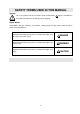
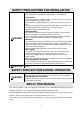
SAFETY TERMS USED IN THIS MANUAL Symbol This is the symbol used for precautions. Read carefully where appears and follow the instructions to avioid injury or damage to your property. Signal Words Signal Words, “Danger”, “Warning”, and “Caution”, identify safety messages to the reader, and these words mean the followings; Important information to alert you to a situation that might cause loss of life and serious injury.
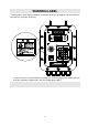
WARNING LABEL A warning label is affixed to the product to call attention for the risk of explosion. Do not remove the label and keep it readable at all times. * The picture above is of Type A model for weighing in the customer programmed control mode and the built-in automatic program mode.) with the Conduit fittings options.
SAFETY PRECAUTIONS FOR INSTALLATION The indicator complies with “ExdIIBT5X” specifications for Explosion protected devices. Install and use the indicator in a proper place to avoid explosion. Environments • Install and operate the indicator in Zone 1 or Zone 2. Never use in Zone 0. • Do not install the unit in direct sunshine. • Avoid vibration, sudden temperature changes, wind, water, or excessive dirt.
1. INTRODUCTION The AD-4403-FP/ ST is an Explosion protected weighing indicator to be installed and used in hazardous area: Zone 1 and Zone 2 where explosive gas exists in the air. It complies with the requirements from IEC (International Electrotechnical Commission) standard: Qualification number: C13526) 1-1 Features • Complies with “ExdIIBT5X” specifications for explosion protected devices (Qualification number: C13526 ) • High speed sampling — 100 times per second.
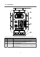
1-2 Front Panel The picture above is of Type A model for normal batching/ loss-in-weigh/ nozzle controlled weighing mode) with the conduit fitting option. # Name [1] [2] [3] Hooks Display Buzzer [4] Operation Keys [5] Conduit fittings Description Used for lifting. Displays weight, status, and messages. See {1-3 Display} Sounds for a warning or when weighing completes. (selective) Tare, Zero, and set / call / recall Set point and do settings. Two kinds of Overlay: Type A and Type B.
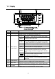
1-3 Display # Name [1] Main Display [2] Sub display Description A 7-digit 7-segment display. Displays gross weight, net weight, etc An 8-digit 7-segment display. The display content can be selected at function settings. See {Appendix C: Function List } “—“ [ZERO] [3] Status display section (upper) [4] Status display section (lower) [5] Right LEDs [6] Left LEDs The upper “—” mark indicates the status of the weight. Illuminates at the center-zero. [STABLE] • Illuminates at a stable reading.
1-4 Operation Keys Type A for the normal batching/ loss-in-weigh/ nozzle controlled weighing mode. # [1] [2] Name [ZERO] [7] [UNDER] [ANF] [3] [4] [TARE] [8] [OVER] [CALF] [5] [6] [GROSS/NET] [9] [PRESET TARE] [7] [ON/OFF] [8] [SET POINT] [9] [FUNC.] [10] [6] [FULL] [RSF] Description Returns the display to the center of zero. The range of zero can be set at CALF-05. See { Appendix C: Function List} Works as a numerical key, 7, used for settings. Selects the “under limit” weight.
# Name [11] [12] [ENTER] [F] [13] [ESC] [14] [3] [PRELIM] [INF] [15] [16] [+/-] [2] [FREE FALL] [SQF] [0] [17] [18] [19] [20] [CODE] [1] [FINAL] [FNCF] [5] [ZERO BAND] [SIF] [4] [OP. PRELIM] [OUTF] Description Writes a value into memory or ends the setting. Selects item. See FncF-02 {Appendix C: Function List}. • Returns to the previous status. • Escapes from the current operation. • Mutes the sound of the buzzer. Works as a numerical key, 3, used for settings.
Type B for the check-weighing mode. # [1] Name [ZERO] [7] [2] [3] [4] [5] [6] [ANF] [TARE] [8] [CALF] [GROSS/NET] [9] [PRESET TARE] [7] [ON/OFF] [8] [SET POINT] [9] [FUNC.] [10] [6] [ZERO BAND] [RSF] Description Returns the display to the center of zero. The range of zero can be set at CALF-05. See { Appendix C: Function List} Works as a numerical key, 7, used for settings. Enters the analog output (OP-07) mode. See {8-4 Option-07:Analog Output} Subtracts the tare.
# Name [11] [ENTER] [12] [F] [13] [ESC] [14] [3] [Go] [INF] [15] [16] [+/-] [2] [Hi] [SQF] [0] [17] [18] [19] [20] [CODE] [1] [Hi-Hi] [FNCF] [5] [Lo-Lo] [SIF] [4] [Lo] [OUTF] Description Writes a value into memory or ends the setting. Selects an item. See FncF-02 {Appendix C: Function List}. • Returns to the previous status. • Escapes from the current operation. • Mutes the sound of the buzzer. Works as a numerical key, 3, used for settings.
1-5 Inside the Case # [1] [2] [3] [4] [5] [6] Name Calibration disable switch Wiring label Control signal terminals Description Disables the calibration function. ON Calibration enabled OFF Calibration disabled Shows cable connections. For control signal cables. Turns on and off the power to the unit. Keep the switch on during use. Use the main power switch outside to turn the power off.
2. INSTALLATION 2-1 Precautions The indicator complies with “ExdIIBT5X” specifications for Explosion protected devices. Install and use the indicator in a proper place to avoid explosion. Environments • • • • Install and operate the indicator in Zone 1 or Zone 2. Never use in Zone 0. Do not install the unit in direct sunshine. Avoid vibration, sudden temperature changes, wind, water, or excessive dirt. Operate in environments with temperatures of between -5°C to 40°C and humidity of between 45% and 85% R.
2-2 Wiring Open the front panel door removing screws on the front panel, and connect a power cable, load cell cables, and control signal cables to the terminals inside the case. Follow the instructions below. Cable used Load cell Control signal cable The use of a 6 wire shielded cable is recommended in order to reduce weighing error. (When using a 4-wire cable, connect pin # 34 to # 35, and pin # 36 to # 37.
Control signal cable # [1] Name Control Input [2] Control output [3] OP-07 (Analog output) [4] OP-03 (RS-422/485) OP-04 (RS-232C) Pin # 1 2 3 4 5 6 7 8 9 10 11 12 13 14 15 16 17 18 19 20 21 22 23 24 25 Name Common. Connected inside.
Before closing the door Place the cable on the heat sink board to avoid pinching the cable when closing the door.
2-3 Installing Conduit Fittings Option OP-10 - 14 Affix conduit fittings to the unit following the instructions below. # Parts Name [1] [2] [3] [4] Lock nut Gasket Conduit fitting Sealing tape Procedures 2-5 1: Wind the [4] Sealing tape around the [3] Conduit fitting. 2: Insert into the SERIAL hole through the [2] Gasket. 3: Tighten it with the [1] Lock nut.
2-4 Installing Wall-Mounting Fittings WARNING The fittings have been attached temporally when shipped. Before use, affix the wall-mounting fittings securely to the back of the unit with screws. Be sure to apply some threadlocker to the screws after fastening the screws to avoid loosened screws that may cause accidents. Install the wall-mounting fittings following the instructions below.
[Blank page] 2-7
3. OPERATION 3-1 Turning the Power On • Turning on the power switch inside the case illuminates all the display for 2 seconds, then to normal display. • [ON/OFF] turns the display on and off, not the power supply. • When the power is turned OFF with “O” indicated (OFF mode), “O” will be displayed when turned ON next time. And when turned off with a weight display (Normal mode), it displays the weight. • This manual explains the operation based on the normal mode. 3-2 Basic Operation Action To set Zero.
3-3 Setting and Recalling Set points Setting set points 1. Enter the set point setting mode. Press [CODE] [code number (2 digits)] [SET POINT] [ENTER] in this order. It shows; Main display: Sub display: Status display section (lower): Left LEDs: * * * “CodE XX” “YYYYYY” “FINAL” mark turns on. “SET POINT” LED blinks. Use numerical keys ([0] – [9]) to type a code number. Set a blank for the code number with [+/-] to change the set point in use. Press [ESC] to return to the normal mode. 2.
3-4 Recalling through Clearing Accumulation data 1. Recall the accumulation data (weight and count). Press [CODE] [code number (2 digits)] [F] in this order. It shows; Main display: “CodE XX” (Code number) Sub display: “YYYYYY” (Accumulated weight) Left LEDs: “TOTAL” LED turns on. * * * Use numerical keys ([0] – [9]) to type a code number. Press [ESC] to cancel the input and re-input. Or erase the digits typed with [+/-] and continue typing. Press [ESC] to return to the normal mode.
3-5 Editing Accumulation data Set point editing modes There are 8 modes for editing set point data. Mode # Mode name Description [0] Mode 0 [1] Mode 1 [2] Mode 2 [3] [4] Mode 3 Mode 4 [5] Mode 5 Retrieves the code number with no set point data setting. Writes set point data over the set point designated by a code number. Clears the set point and accumulation data designated by a code number. Clears the accumulation data designated by a code number.
Procedures for each mode Mode # Name Description Display [0] Mode 0 Retrieves the code number with no set point data set. “CodE bL” Press [ENTER] to display the code number with no set point data It returns to the set point editing mode after the action. “SEArch ” * Press [ESC] to select another mode. “SET POINT” LED: ON Writes set point data over the set point designated by a [1] Mode 1 code number. “CodE CP” Input a 2-digit code number: “XX” to be copied, “YY” to be “XX to YY” written over.
Mode # [4] * * * Name Mode 4 Description Display Displays all the set points that have been set. “CodE ” Input the 2-digit code number of the data to be displayed. Press [+/-] to cancel the input and re-input. “ALL diSP” Press [ESC] to return to the set point editing mode. Press [F] [ENTER] to display the set point data designated by the code number. Press [F] to jump to a code with no set point data. The type of set point is not changed. Press [ENTER] several times to select a type of set point.
4. CALIBRATION Section related: {Appendix C:FUNCITON LIST: CALF―Calibration Functions} {Appendix B:Erro codes} 4-1 General There are three ways to calibrate zero and span. Digital span calibration Calibrates with load cell output voltage. Actual load calibration Calibrates with weights. Gravity compensation Sets the know acceleration rate (“g”) for your location 4-2 Digital Span Calibration This is calibration using the load cell output voltage (mV/V) instead of weights.
Actual load calibration procedures Calibration procedures vary by the type of calibration. Follow the step number in the table below to calibrate. * When “C ErrXX” is displayed, there is something wrong with the calibration. See {Appendix B: Error Codes}. Zero calibration only Span calibration only Zero and Span calibration Get in the calibration mode. 1 1 1 * Press [CALF] while pressing [ENTER] in the normal mode, and press [ENTER] next. “CAL Set” is displayed.
4-4 Gravity compensation 1. Get in the calibration mode * Press [CALF] while pressing [ENTER] in the normal mode, and press [ENTER] next. “CAL Set” is displayed. (ready to calibrate) Press [ESC] to return to the normal mode. * Press [FUNC.]. “GrAvity” is displayed on the main display and your “g” value is on the sub-display.. Press [ESC] to return to the normal mode. * * Refer to {Appendix D: Gravity acceleration map} and enter the value on the map. Press [ENTER] to save the calibration data.
5. FUNCTION SETTINGS Section related: {Appendix C: Function list:} The functions determine the operations of the indicator and each function is sorted into the groups by capabilities and represented by prefixing its group name. * All the function setting are done in the same manner except for FuncF-01. * All the setting information is stored in the EEPROM.
5-2 Function Settings 1. Enter the function setting mode. * * Press [FUNC.] for 0.3 seconds or longer in the normal mode. “Function” is displayed on the sub display. [FUNC.] will not work unless pressed for 0.3 seconds or longer. Press [ESC] to return to the normal mode.. 2. Press a function key. * Select and press a function key from the table {5-1. General} to set or see function setting information. If the wrong key pressed, press [ESC] and return to the normal.
6. WEIGHING Section related: {Appendix C: Function List—CALF-14} 6-1 Weighing value and Set point Weighing is performed comparing the weighing value with “Set point” values, and the weighing process is controlled by input and output signals. Type of weighing values There are 2 types of weighing values: Display count and internal count. (Selectable in SqF-01) • “Display count” is the value on the display. • “Internal count” is a high-resolution value calculated with a minimum division of 1.
6-2 Weighing Modes The indicator-FP has 10 weighing modes, which vary from the weighing method (normal batching or loss-in weigh) and with/without a PLC (Programmable Logic Controller). Choose the mode suitable for your weighing at CALF-14. (See {Appendix C: Function List}) Utility PLC.
[Blank page] 6-3
6-3 CALF-14=“1” Weighing Mode (Normal batching in customer programmed control mode) Output signal Output condition Zero band Full-flow medium-flow Dribble-flow Over limit Under limit Final Final Final Final - Optional preliminary Preliminary Free fall + Over limit ≤ ≤ ≤ < Gross weight ≤ Zero band Net weight Net weight Net weight Net weight Net weight < Final - Under limit • When an output condition is established, a relevant output terminal is turned on (power continuity with output COM).
6-5
6-4 CALF-14=“2” Weighing Mode (Loss-In-weigh in customer programmed control mode) Output signal Output condition Zero band Full Full-flow Medium-flow Dribble-flow Over limit Under limit Full Final - Optional preliminary Final Preliminary Final Free fall Final + Over limit ≤ ≤ ≤ ≤ < Gross weight Gross weight - Net weight - Net weight - Net weight Net weight - Net weight ≤ Zero band < Final - Under limit • When an output condition is established, a relevant output terminal is turned on (power continuit
6-7
6-5 CALF-14=“3” Weighing Mode (with no Supplementary Flow) (Normal batching in built-in automatic program mode) Output signal Output condition Zero band Full-flow Medium-flow Dribble-flow Over limit Under limit Final Final Final Final - Optional preliminary Preliminary Free fall + Over limit ≤ ≤ ≤ < Gross weight ≤ Zero band Net weight Net weight Net weight Net weight Net weight < Final - Under limit • When an output condition is established, full flow, medium flow, and dribble flow outputs are turned
Note * In the case of built-in-automatic program mode weighing, the set point data is held until batch finish since batch start. Therefore, a set point altered during batching takes effect after “batch finish” is output. * “Within limit” is on in the chart above.
6-6 CALF-14=“3” Weighing Mode (with Supplementary Flow) (Normal batching with supplementary flow in built-in automatic program mode) Supplementary flow automatically turns on the dribble flow for the specified time when the loaded weight is not sufficient. To make supplementary flow, set the “maximum supplementary flow times, SQF-08,” to other than 0, and the “supplementary flow open timer, SQF-16,” and “supplementary flow close timer, SQF-17,” to their respective times.
Note * In the case of built-in-automatic program mode weighing, the set point data is held until batch finish since start of batching. Therefore, a set point altered during batching takes effect after “batch finish” is output. * The chart above is the case that a judgement result becomes “Within limit” at the third judgement after supplementary flow action has been made twice.
6-7 CALF-14=“4” Weighing Mode (Loss-In-weigh in built-in automatic program mode) Output signal Output condition Zero band Full Full-flow Medium-flow Dribble-flow Over limit Under limit Final Final Final Final Full - Optional preliminary Preliminary Free fall + Over limit ≤ ≤ ≤ ≤ < Gross weight Gross weight Net weight Net weight Net weight Net weight Net weight ≤ Zero band < Final - Under limit • When an output condition is established, full flow, medium flow, and dribble flow outputs are turned off
Note * * SQF-21/ SQF-22 setting enables to add automatically the Final weight to Zero band or Full. Therefore there is always enough ingredient left in the hopper for a measurement. In the case of built-in-automatic program mode weighing, the set point data is held until batch finish since start of batching. Therefore, a set point altered during batching takes effect after “batch finish” is output.
6-8 CALF-14=“5” Weighing Mode (Nozzle controlled weighing mode) Output signal Zero band Full-flow Medium-flow Dribble-flow Over limit Under limit Final Final Final Final Output condition - Optional preliminary Preliminary Free fall + Over limit ≤ ≤ ≤ < Gross weight Net weight Net weight Net weight Net weight Net weight ≤ Zero band < Final - Under limit • When an output condition is established, a relevant output terminal is turned on or off.
Note * * * In the case of built-in-automatic program mode weighing, the set point data is held until batch finish since start of batching. Therefore, a set point altered during batching takes effect after “batch finish” is output. Chart above is of the case; • “Acceptable weight” is on. • A judgement result becomes “Acceptable weight” at the third judgement after supplementary flow action has been made twice.
6-9 CALF-14=6 Weighing Mode (Check weighing 1) Output signal Zero band Hi-Hi Hi Go Lo Lo-Lo Target weight + Target weight - Output condition Hi-Hi limit Hi limit Lo limit Gross weight < Net weight < Net weight ≤ Net weight Net weight Net weight ≤ Zero band ≤ Target weight < Target weight < Lo-Lo limit + Hi limit - Lo limit • When an output condition is established, a relevant output terminal is turned on (power continuity with the output common) or off.
6-10 CALF-14=7 Weighing Mode (Check weighing 2) Output signal Zero band Hi-Hi Hi Go Lo Lo-Lo Target weight Target weight Target weight Target weight Output condition + Hi-Hi limit + Hi limit Lo limit - Lo-Lo limit < < ≤ ≤ Gross weight Net weight Net weight Net weight Net weight Net weight ≤ ≤ ≤ < < Zero band Target weight + Hi-Hi limit Target weight + Hi limit Target weight - Lo limit Target weight - Lo-Lo limit • When an output condition is established, a relevant output terminal is turned on (power
6-11 CALF-14=8 Weighing Mode Check weighing 3) Output signal Zero band Hi-Hi Hi Go Lo Lo-Lo Output condition Hi-Hi limit Hi limit Lo limit Gross weight < Net weight < Net weight ≤ Net weight Net weight Net weight ≤ Zero band ≤ Hi limit < Lo limit < Lo-Lo limit • When an output condition is established, a relevant output terminal is turned on (power continuity with the output common) or off. “Full flow”, “Medium flow”, and ”Dribble flow”: OFF, the other outputs: ON.
6-12 CALF-14=9 Weighing Mode Check weighing 4) Output signal Zero band Hi-Hi Hi Go Lo Lo-Lo Output condition Hi-Hi limit Hi limit Lo limit Lo-Lo limit ≤ ≤ ≤ ≤ Gross weight Net weight Net weight Net weight Net weight Net weight ≤ Zero band < < < < Hi-Hi limit Hi limit Lo limit Lo-Lo limit • When an output condition is established, a relevant output terminal is turned on (power continuity with the output common) or off. “Full flow”, “Medium flow”, and ”Dribble flow”: OFF, the other outputs: ON.
[Blank page] 6-20
7. OTHER FUNCTIONS 7-1 Auto Print Section related:{Appendix C: Function list: SiF—Standard Serial Output Functions: SiF 02} {Appendix C: Function list: SiF— rSF: OP-03 (RS-422/485), OP-04 (RS-232C): rSF -02} Auto print is the capability to output the Batch Finish weight from the external output configured to “Auto Print”. The output timing depends on the weighing mode.
7-3 Automatic Free Fall Compensation Section related: {Appendix C: Function List {Appendix C: Function List—Sq F: Weighing Sequence Functions, Sq F-03, 04, 29} In batch weighing, the actual Free Fall {Weight at batch finish - (Final weight – Free Fall weight)} is not equal to the value of the Free Fall setting.
8. INTERFACE 8-1 Control Input / Output Section related: {Appendix C: Function List—InF: Control Input Functions} {Appendix C: Function List—outF: Control Output Functions} The Control Input / Output interface, consists of 6 inputs and 6 outputs, is intended for inputting/outputting weighing control signals to an external unit. The capability of each input/output terminal can be selected at its function setting, except COM (common).
Specifications Input circuit Maximum Input Voltage Maximum input current Contact +12 V 3 mA approximately Relay contact or Open collector Output circuit Maximum input voltage Maximum input current 220 V AC/ 24 VDC 0.5A (AC)/ 0.
8-2 Standard Serial Output Section related: {8-6 Data Transmitting Format data} {Appendix C: Function List—SiF: Standard Serial Output Functions} The standard serial output is a 20-mA current loop interface for connection of a remote indicator or printer to the indicator. This output does not have a power supply, an external power supply is required.
8-3 Option (OP-03: RS-422/485, OP-04: RS-232C) Section related: {8-6 Data Transmitting Format data} {Appendix C: Function List— rSF: OP-03 (RS-422/485), OP-04 (RS-232C) OP-03 (*RS-422/485) and OP-04 (RS-232C) provides external inputs/outputs to be connected to a personal computer and other peripherals. * OP-03 can be switched between RS-422 and RS-485.
Address capability (OP-03: RS-422/485) Section related: {Appendix C: Function List— rSF: OP-03 (RS-422/485), OP-04 (RS-232C: rSF-09) The address capability responds only when a specific unit is called from a host computer. The address number of each unit can be set from 1 to 99 with RSF-09; 0 denotes no address capability. When a command prefixed with an address “@xx”(xx is an address number) is sent from the host computer, each indicator compares this with the address setting of the individual instrument.
Example Note: * The polarity of signal A and B vary from computers. * Not necessary to ground the SG (Signal Ground) terminal to a computer if no SG terminal. * Set 8 ms or more for the SDA and SDB signal interval.
8-4 Option (OP-07 Analog Output) Section related: {8-6 Data Transmitting Format data} {Appendix C: Function List— AnF: Analog Output Functions) The OP-07 analog output option is for sending weight data to the analog input unit. The output is a 4 to 20 mA current output proportional to the display reading. * The output data is updated in synchronization with the display update. Interface specifications Output current 4 - 20 mA Applicable load 0 - 520 Ω resistance Resolution 1/3000 approx.
8-5 Data Transmitting Mode OP-03/04 covers all transmitting modes. However standard serial output does not. See the table below. Stream Standard serial output OP-03:RS-422/485, OP-04:RS-232C Auto print Manual print Accumulation timing print Command Output per Sampling The data is transmitted in synchronization with the update of the display. When the display rewrite exceeds the baud rate, data transmission is suspended until the next display update.
8-6 Data Transmitting Format Item of data →Description ↓Item Header1 Header2 Header3 Separator Data (ASCII) Code number Weighing unit Terminator ASCII code Hex.
Data format Format Type Form A Format Name A&D Standard Data Format Standard format for A &D products like weighing indicators and printers. 18 characters in all Example (Stable, Gross weight: +12345kg) Head 1 S T , Head 2 Data G S , + Unit 0 0 Form B 1 2 3 4 5 k Term. g C L R F A&D Standard Data Format with Code Number 24 characters in all Example (Code number: 00, Unstable, Net weight: -123.
Format Type Form E Format Name Set Point Setting Format Terminator Preset Tare +1763 +0001763 • • Type B model for the Check weighing This format is available only in command mode. Data length: 76 bytes ( 60 bytes) Set “SSXX” command ignoring decimal point. Decimal point will cause an error. “RSXX” command ignores decimal point.
Format Type Form H Format Name Weighing Condition Read-Out Format Example Positive Overflow, Weight Data: 7FFFFF Weighing data 6 digits, hexadecimal 30 37 46 46 46 46 46 CR 0 0 1 1 X X X X Fixed Fixed Zero band 30 Fixed 30 Terminator Fixed Set Point data 0 1 1 X LF Weighing data Weighing data is described in 6-digit hexadecimal ignoring decimal point. 999.9 kg → 00270F (Hex) -0.
8-7 Command Mode The indicator receives a command transmitted from a peripheral unit like a computer in the communication procedure shown below, and operates in compliance with the command and responds with a result. * The communication procedure depends on the type of command. * When the command is not accepted due to an error (improper command or faulty data), a “negative acknowledgment” is made.
Commands * See {8-6 Data Transmitting Format —Data Format} for “Data Format”. * See {8-7 Command Mode— Communication procedure} for “Procedure”. Command Command name RW (Request Weight) Function Procedure Recalls the weight B Data Format A/B • The content of the response data is the same as that set with RSF-01. • Same operation as when the manual print key is pressed. MZ (Make Zero) Zero clear A MT (Make Tare) Subtracts the tare A Subtracts the tare. Display shows the net weight.
* See {8-6 Data Transmitting Format —Data Format} for “Data Format”. * See {8-7 Command Mode— Communication procedure} for “Procedure”. Command Command name HB (Halt Batch) Function Procedure Halt batch in an emergency A Data Format • This command is available only in the built-in automatic program mode weighing. • In other weighing mode, "IE" will be transmitted. RF (Request Final) Recalls the final weight B A/B Outputs the net weight at batch finish. RB (Req.
Programming in RS-422 * Example: Recalls the weighing data from two indicators.
Programming in RS-232C Settings Personal computer Baud rate Parity Character bit length Stop bit length Terminator 9600bps Even 7 bits 1 bit CR,LF Indicator Baud rate Parity Character bit length Stop bit length Terminator Output data 9600bps Even 7 bits 1 bit CR,LF Displaying weight Data transmitting mode command Address number None 10 OPEN “COM:E71NN” AS #1 RS-232C setting rSF-03=5 rSF-04=2 rSF-05=7 rSF-06=1 rSF-07=2 rSF-01=1 rSF-02=5 rSF-09=0 20 PRINT #1,”RW” Requests the weight to the Indicator.
[Blank page] 8-18
9. MAINTENANCE 9-1 System check Check items Following 12 items can be checked in this check mode. Display in the check mode “Chc PrG” “Chc Ad” “Chc KEy” “Chc LEd” “Chc buZ” “Chc EEP” “Chc bAt” “Chc Si” “Chc in” “Chc Out” “Chc rS” “Chc An” Check item Program version A/D converter Key switches Display Buzzer EEPROM Lithium battery Standard serial output Control input Control output RS-232C/422/485 Analog output General procedures 1.
Each check item Display “Chc PrG” Check Item Program Version This check displays the version of the program stored in the ROM. The version number is displayed as “vEr X.XX”. * Press [ESC] to return to the check item-selecting mode. “Chc Ad” A/D Converter The load cell Input voltage is displayed in the unit of mV/V. Applying offset voltage to the load cell can check the A/D Converter function. Keep the record of the input voltage for future maintenance work. * Apply some voltage with [F] and [ENTER] .
Display “Chc LEd” Check Item LEDs Pressing [F] or [ENTER] shows a relevant number of the LED as “no.XX” and illuminates the * LED. To return to the check item-selecting mode, press [ESC]. LED Display “no. 1” “no. 2” “no. 3” “no. 4” “no. 5” “Chc buZ” Buzzer Pressing [ENTER] sounds the built-in buzzer and displays “buSy” while sounding. SET POINT TOTAL ACCEPT OVER UNDER * * To return to the check item-selecting mode, press [ESC].
Display “Chc Out” Check Item Control output (Terminal #10 to #19) Turns on a terminal #10 to #19 in this order and displays a relevant terminal-number as shown below. (This check is performed automatically.) * Ignore these displays, “J11 6” , “J11 4” , “J11 2” . They are for factory use. * To return to the check item-selecting mode, press [ESC].
9-3 Initialization You will lose all the setting data stored in the memory by initializing. The lost data can not be retrieved. Initialization swaps all the data stored in the memory in the RAM and the EEPROM with the default data that factory has configured originally. There are 3 types of initialization depending on items to be initialized. The item marked with “√” in the table below will be initialized.
APPENDIX A: SPECIFICATIONS Specifications A/D Converter Block Input sensitivity Zero correction range Load cell excitation Zero point Temperature coefficient Sensitivity Non-linearity Input noise Maximum measurement voltage A/D conversion method A/D internal resolution Sampling speed Maximum display resolution 0.3μV/D or more 0 – 20mV (0 - 2mV/V) 10 VDC±5%, 120mA with remote sensing capability Up to four 350Ω load cells can be connected ±(0.2μ+0.0008% of Dead Load)/ typical ±0.0008%/°C typical ±0.01% F.S.
Interfaces Control I/O Standard serial output(C.LOOP OUT) • 6 points (6 bits, 2 Commons) • Dry contact or open collector Input (CONTROL IN) • Signal is insulated from an internal circuit by an optocoupler. • Terminal functions selectable by the function settings • 6 points (2 bits, 1 Common x 3) • Relay contact output Output (CONTROL • AC current output available OUT) • Rating: 24 VDC, 0.5 A (Resistance load), 220 VAC, 0.
General specifications Structure Data backup Buzzer Supply voltage Power consumption Fuse Operating temperature & humidity Storage temperature & humidity Weight (accessories not included) Dimensions • Anti explosion structure • Type: ExD BT5 (Inspection qualified number: “C13526” • Zero point correction value, tare value, set point, accumulated weight backup by a lithium battery (Approx. 10 years) • An alarm indicator lamp is turned on when the battery is running out.
Dimensions: Indicator (Unit: mm) * Picture above is of type A model with conduit fitting options (OP-10-14) installed.
Dimensions: OP-20 Stand A-5
Mounting Dimensions (Unit: mm) * Picture above is of type A model with conduit fitting options (OP-10-14) installed.
[Blank page] A-7
APPENDIX B: ERROR CODES Error code “C Err 0” Causes Solutions “C Err 2” The minimum graduation is other than 1, 2, 5, 10, 20, and 50. Resolution (weighing capacity divided by minimum graduation) is more than 16000. The voltage of the zero calibration point is overloaded in the positive direction. “C Err 3” The voltage of the zero calibrated point is overloaded in the negative direction. “C Err 1” “C Err 5” “C Err 6” The calibration weight is more than the weighing capacity.
[Blank page] B-2
APPENDIX C: FUNCITON LIST Section related: {5. Function settings} FncF—Basic Functions Function # FncF -01 0 1 Function name key Operation Default 0 Not disabled Disable 0 0 0 0 0 0 0 ↑ ↑ ↑ ↑ ↑ ↑ ↑ ↑ [ENTER] [FUNC.] [SET POINT] [ON/OFF] [NET/GROSS] [TARE] [ZERO] Key 0 [+/-] Status display (lower) Press a key to be disabled, then press [F] to disable. When disabled, a relevant digit becomes “1” (Disabled). When [FUNC.] is disabled To perform function settings, press [FUNC.
Function # FncF-04 0 1 2 3 4 5 6 Function name Sub display Default 0 None Gross weight Net weight Tare weight , Preset tare weight Final Total accumulated weight Total accumulated count display FncF-05 0 1 2 3 4 5 6 7 8 9 Range 0 None “Discharging” (Only effective in normal batching in the built-in automatic program) “Zero tracking” “Weighing” “Weighing error” Input acknowledgement “Zero error” “Accumulation over” “Low battery” “Converting weighing unit” FncF-06 0 1 2 3 None 11.0Hz 8.0Hz 5.
Function # FncF-10 0 1 Disable Not disabled FncF-11 0 1 2 1 Preset tare without code number can be recalled in spite of the setting of “0”. When there is no tare data to be recalled, previous tare weight will be used. When there is no tare data to be recalled, it clears the tare data.
Sq F—Weighing Sequence Functions The SqF functions are available only for the mode specified in the note column and each mode name is described as shown below. Not specified functions are available for all the weighting sequences.
Note Function # Range Default Auto Sq F-14 0.0 - 25.5 (sec.) 0.0 Auto Sq F-15 Batch monitoring timer 0 – 255 (sec.) 0 Auto Sq F-16 Supplementary flow open timer 0.01 - 2.55 (sec.) 0.10 Auto Sq F-17 Supplementary flow close timer 0.1 - 25.5 (sec.) 0.1 Auto Sq F-18 Discharge start wait timer 0.0 - 25.5 (sec.) 0.0 Auto Sq F-19 Discharge valve close wait timer 0.1 - 25.5 (sec.) 0.1 Auto Sq F-20 Discharging time monitor timer 0 - 255 (sec.
Note Function # Sq F-27 0 1 2 3 4 5 6 7 8 9 10 11 12 13 Function name Buzzer Disable Full-flow (Go) Medium-flow (Lo) Dribble-flow (Lo-Lo) Over limit (Hi) Acceptable weight Under limit (Hi-Hi) Zero band Batch finish Weighing sequence running Full Stable Over limit/under limit Weighing sequence error Sq F-28 Range Default 0 The built-in buzzer sounds synchronized with the selected signal for the period of time Sq F-28 has determined.
In F—Control Input Functions Function # Function name in F-01 - 06 Control Input; Capability of pins #1 to #9 of the control signal terminals inside the case. 0 1 2 3 4 5 6 7 8 9 10 11 12 13 14 15 16 No capability Zero Tare Batch start Emergency stop Discharge start Key enable Automatic free fall command Tare clear Accumulation command Cancel previous accumulation Total accumulated weight clear Clear both total accumulated weight and accumulated weight of the code used now.
outF—Control Output Functions 0 1 2 3 4 5 6 7 8 9 10 11 12 13 14 15 16 17 18 19 20 21 Function # Function name outF-01 - 06 Control output; Capability of pins #10, 11, 14, 15, 18, and 19 of the control signal terminals inside the case.
SiF—Standard Serial Output Functions Function # SiF-01 1 2 3 4 5 6 7 8 1 Baud rate (bps) 2 Code number output 0 600 bps 2400 bps SiF-04 0 1 Data transmitting mode Stream Auto print Manual print Accumulation timing print SiF-03 1 2 Output data Default 1 Displayed weight Gross weight Net weight Tare Gross weight/net weight/tare Accumulated weight Accumulated count Accumulated weight/accumulated count SiF-02 1 2 3 4 Function name None Output data with its code number C-9
rSF—OP-03:RS-422/485/ OP-04:RS-232C Functions Function # rSF-01 1 2 3 4 5 6 7 8 6 7 Baud rate bps 5 Parity 2 Character bit length 7 Stop bit length 1 Terminator 2 RS-422/485 switching 1 RS-422 RS-485 rSF -09 This setting is invalid when the RS-232C is used. Address number 0 No address capability 01 - 99 With address capability rSF -10 0 1 Data format: form H (Weighing Condition Read-Out Format) See {8-6:data format}. rSF -08 1 2 Set to 9600 bps or less.
AnF—Analog Output Functions Function # AnF-01 1 2 3 Function name Output data Range Default 1 Displayed weight Gross weight Net weight AnF-02 Weight at 4 mA output -999999 - 9999999 0 AnF-03 Weight at 20 mA output -999999 - 9999999 10000 C-11
CALF—Calibration Functions ST: In case of the ST series, do not change the settings. If changed, weighing will not be performed properly. Function # CALF-01 ST 0 1 2 3 Range Default 2 None g kg t CALF-02 ST 0 1 2 3 4 Function name Weighing unit None 1 10 2 10 3 10 4 10 CALF-03 ST Decimal point position 0 1 2 3 4 5 1 2 3 4.5 1 2 3.4 5 1 2.3 4 5 1.2 3 4 5 Minimum division 1, 2, 5, 10, 20, 50 (D) 1 Minimum division (D) for the weight. Input 1, 2, 5, 10, 20, or 50(decimal point ignored).
Function # CALF-06 CALF-07 Function name Zero Tracking Time Zero Tracking Width Range 0.0 - 5.0 (sec.) 0 – 9 (1/2D) Default 0.0 0 Zero tracking compensation function will automatically bring the display back to zero when there are small deviations. This function is set in combination with CALF-06 and CALF-07. * * Zero tracking is not performed with CALF-06=0. Its least input increment is 1/2D.
Function # CALF-08 CALF-09 Function name Motion detection time Motion detection width Range 0.0 - 5.0 (sec.) 0 – 9 (1D Default 1.0 2 These settings modify the “Stable” condition by the counts per time of non-movement before the indicator recognizes the stable condition. The fewer counts per longer time are more likely to recognize the stable condition and vice versa. * * Motion detection function is not performed with CALF-08=0. “D” is minimum division.
Function # CALF-14 1 2 3 4 5 6 7 8 9 Range Normal batching (Customer Programmed Control Mode) Loss-in-weight (Customer Programmed control Mode) Normal batching (Built-in automatic program mode) Loss-in-weigh (Built-in automatic program mode) Nozzle Controlled Weighing Mode (Built-in automatic program mode) Check weighing 1 Check weighing 2 Check weighing 3 Check weighing 4 CALF-15 0 1 Function name Weighing mode Default 3 See {6. Weighing} in detail.
ST : In case of the ST series, do not change the settings. If changed, weighing will not be performed properly. Function # CALF-19 ST Function name Zero Input Voltage Range 0.000000 - 2.200000 (mV/V) Default 0.000000 Input Voltage (mV/V) from the Load Cell at "Zero", which is determined in "Zero Calibration" with weights.—Actual load calibration CALF-20 ST Span Input Voltage (Capacity to zero) 0.000000 - 3.2000000 (mV/V) 3.
APPENDIX D: GRAVITY ACCELERATION MAP Amsterdam Athens Auckland NZ Bangkok Birmingham Brussels Buenos Aires Calcutta Chicago Copenhagen Cyprus Djakarta Frankfurt Glasgow Havana Helsinki Kuwait Lisbon London (Greenwich) Los Angeles Madrid 9.813 9.800 9.799 9.783 9.813 9.811 9.797 9.788 9.803 9.815 9.797 9.781 9.810 9.816 9.788 9.819 9.793 9.801 9.812 9.796 9.
Fig Apx-D-02 Gravity map.
APPENDIX E: DATA OUTPUT EXAMPLES Output conditions Terminator Control code Code number Final (Go) Free fall (not in use) Preliminary (Hi-Hi) Optional preliminary (Lo-Lo) Over limit (Hi) Under limit (Lo) Zero band Full (not in use) Preset tare Other code number
(0DH or 0D0AH) (1AH) 1 500.0kg 10.0kg 120.0kg 350.0kg 10.0kg 20.0kg 0.5kg 1000.0kg 123.Form F * Factory setting: rSF-02 = “5” (Command mode) Address: “None” (rSF-09=0) Address : “1” (rSF-09=1) E-2
Form G Address: “None” (rSF-09=0, CALF-14=1~5, Customer Programmed Control Mode/ Built-in automatic program mode weighing) Address: “1” (rSF-09=1, CALF-14=1~5, Customer Programmed Control Mode/ Built-in automatic program mode weighing) E-3
Address: “None” (rSF-09=0, CALF-14=6~9, Check weighing) Address: “1” (rSF-09=1, CALF-14=6~9, Check weighing) Reading data out from EEPROM (rSF-09) Address: “None” (rSF-09=0) Address: “1” (rSF-09=1) E-4
APPENDIX F: USER’S SETTING RECORD Keep all the setting information for future maintenance. Function Setting Record Func. # Function Name Value FncF: Basic Functions Func.
Section in in in in in in Function Value in F: Control I/O—Input F-01 F-02 F-03 Pin #1 to #9 of control signal terminal F-04 inside the case F-05 F-06 outF: Control I/O—Output outF-01 outF-02 outF-03 Pin #10, 11, 14, 15, 18, and 19 of outF-04 control signal terminal inside the case.
Set Point Setting Record Item Value Tare Final Free fall Preliminary Optional preliminary Over limit Under limit Zero band Full Dribble-flow time (Use a stop watch to measure) Medium-flow time (Use a stop watch to measure) Full-flow time Target weight Hi-Hi limit Hi limit Lo limit Lo-Lo limit F-3