
Operating instructions

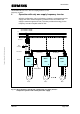

Operation with only one supply frequency inverter
MICROMASTER 420 / 440 – DC link coupling between several
Frequency inverters
4.2 Options required at the line supply input of the supply inverter
The fuses, circuit-breaker and a possible externally mounted EMC filter
should be used, according to Catalog DA51.2, at the line side of the supply
inverter as for frequency inverters operated in the standalone mode.
Frequency inverters with integrated EMC filters can also be used as supply
inverter; for the frequency inverters connected to the DC link, an integrated
EMC filter makes no sense and is not necessary.
In order to ensure reliable operation of the drive group, the supply inverter
must always have a line reactor. The line reactor can be dimensioned using
Catalog DA51.2 just like the frequency inverters which are operated as
standalone units.
Note:
Under certain circumstances it is no longer guaranteed that the EMC limit
value classes are fully maintained. This is the reason that it is absolutely
necessary that the EMC Guidelines, specified in the frequency inverter
Operating Instructions are carefully maintained.
4.3 Engineering the DC link couplings
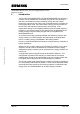
When engineering the DC link couplings, it must be noted that the DC link
current I
DC
, provided by the supply inverter, does not correspond exactly to
the line current I
N
(specified in Tables 2-1 and 2-2). The DC link current I
DC
can be more precisely specified in relationship to the frequency inverter
output current I
A
. The DC link current I
DC
is then given by:
In this case:
I
DC
= DC link current at the DC link terminals of the
frequency inverter
I
A
= frequency inverter output current (motor current)
cosφ
Motor
= motor power factor
V
A
= frequency inverter output voltage
V
max
= max. frequency inverter output voltage
η
INV
= efficiency of the inverter module
Copyright © Siemens AG 2005 All rights reserved
INV
A
MotorADC
V
V
II
η
ϕ
1
cos35.1
max
••••=
A&D SD Page 8/32