
Operating instructions


Introduction
MICROMASTER 420 / 440 – DC link coupling between several
Frequency inverters
3 Introduction
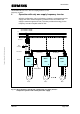
The DC links of MICROMASTER 420 and MICROMASTER 440 frequency
inverters can be coupled with one another using the DC link coupling. In
this case, the frequency inverters exchange energy with one another
through the common DC link. When one or several frequency inverters are
in the regenerative mode, this means that the energy can be provided via
the DC link to the frequency inverters which are motoring . If the
regenerative energy is not completely utilized by the connected frequency
inverters, or not at every instant in time, than this can be dissipated in the
braking resistor using the braking chopper that it is integrated in the
MICROMASTER 440.
As a result of the energy exchange between the frequency inverters, less
energy is drawn from the line supply and, depending on the application,
less or no braking energy is dissipated in the braking resistor.
Drives for winders/unwinders and transport conveyor belts are examples of
typical applications.
With the DC link coupling, either only one frequency inverter or up to three
frequency inverters can be simultaneously connected to the line supply.
Additional frequency inverters can be connected to the supply inverters via
the DC link.
Copyright © Siemens AG 2005 All rights reserved
A configuration with one supply inverter is described in Section 2. This
arrangement is practical if the frequency inverters that are connected
predominantly operate in the regenerative mode or the supply inverter has
a far higher power rating than the connected frequency inverters.
The DC link coupling with several supply inverters connected in parallel (up
to 3 are possible) is described in Section 3. These can be especially used if
several drives which operate in the motoring mode are connected and the
supply power is to be distributed over several frequency inverters.
A&D SD Page 5/32