
Operating instructions

Operation with up to three supply inverters
MICROMASTER 420 / 440 – DC link coupling between several
Frequency inverters
A&D SD Page 30/32
Copyright © Siemens AG 2005 All rights reserved
Note:
o The integrated braking chopper is only active if the frequency inverter
had received an ON command and is actually operational. When the
appropriate frequency inverter is powered-down, then energy cannot be
pulsed in the braking resistor.
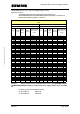
o The braking resistors, which are used in the Catalog DA51.2, are
specified for a duty cycle of 5%. The duty cycle can be increased
corresponding by using several braking resistors with a duty cycle of 5%
or other suitable braking resistors. For the DC link coupling, the
regenerative energy could also be supplied from (several) other
inverters. In this case it must be ensured, that the braking power which
is dissipated in continuous operation in the braking resistor does not
exceed the rated power P
INV
N
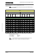
of the braking inverter. The maximum
short-time braking power P
brake
short
can be calculated with the minimum
possible restistance of the braking resistor R
min
(Table 5-4 of the
MICROMASTER 440 Operating instructions) and the maximum possible
DC link voltage V
DC
max
(
DC 420V at 230V-units resp. DC 840V at 400V-units).
This means the following:
P
brake
short
= V
DC
max
² / R
min
For the DC link coupling the highest permitted value of the duty cycle x
in the Parameter 1237 at MICROMASTER 440 is: x ≤ (P
INV
N
/ P
brake
short
) * 100%
The DC braking – function in the inverter can be used as an alternative to
regenerative braking using the integrated braking chopper. This can be
activated for every connected frequency inverter. It is not permissible that
the compound braking is activated. The reason for this is that this can
automatically be switched-in, as a function of the DC link voltage and result
in undesirable braking operations.
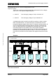
5.5 Max. motor cable lengths
The max. motor cable length of all of the frequency inverters connected in
the DC link group may not exceed, in total, 200m (shielded) and 300m
(non-shielded). Otherwise, their rectifiers and the EMC filters could be
overloaded due to the discharge (leakage currents) which flow with respect
to PE and which flow back through the supply inverter. An output reactor
should be used for the individual frequency inverters for motor cable lengths
exceeding 50m (shielded) and 100m (non-shielded) as specified in Catalog
DA51.2.