
Operating instructions
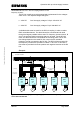

Operation with up to three supply inverters
MICROMASTER 420 / 440 – DC link coupling between several
Frequency inverters
A&D SD Page 29/32
Copyright © Siemens AG 2005 All rights reserved
In this particular case, the five frequency inverters connected to the DC link
are fused with the DC link fuses specified in Table 3-2. The line fuses of the
supply inverters are selected according to the Operating Instructions.
The cable cross-sections to couple the DC link terminals of the inverters to
the DC link fuses are determined corresponding to the downstream DC link
fuses. For the supply inverters, these couplings must be implemented and
routed so that they are short-circuit proof. The couplings after the DC link
fuses are dimensioned for the sum of the rated currents of the line fuses of
the supply inverters multiplied by a factor of 1.2:
I
DCcross-section
= (80A+50A+35A) * 1.2 = 198A
As a result of this current, a cable cross-section of 95mm² was selected.
The cable cross-section required is also dependent on the routing type and
the ambient temperature. In the example, routing type B1, 2 conductors
conducting current in the cable duct and an ambient temperature of 40° C
were assumed.
Note:
For the DC link couplings, it is also important to observe the plant/system
and country-specific standards and regulations.
5.3.3 Maximum DC link cable lengths
The total length of the DC link couplings is 5m.
5.4 Braking operation of the DC link group
For a DC link coupling, energy is exchanged between the frequency
inverters through the common DC link. If one or several frequency inverters
are in the regenerative mode, then the energy can be provided to the
frequency inverters operating in the motoring mode. If the regenerative
energy is not completely drawn by the connected frequency inverters - or
not at every instant in time - then the energy can be dissipated in a
connected braking resistor using the braking chopper integrated in the
MICROMASTER 440.
In a DC link group, the internal braking chopper may only be activated for
one MICROMASTER 440 frequency inverter. It makes sense if the braking
chopper in the MICROMASTER 440 with the highest power rating in the DC
link group is activated. The braking resistor required can be selected in
accordance with the data in Catalog DA51.2.