
Operating instructions

Operation with up to three supply inverters
MICROMASTER 420 / 440 – DC link coupling between several
Frequency inverters
The DC link couplings must be appropriately implemented for the voltages
which occur. The required voltage strength is:
o 450V DC for a line supply voltage of 1/3-ph. 200-240V AC
o 900V DC for a line supply voltage of 3-ph. 380-480V AC
A shielded cable must be used for the DC link coupling in order to reduce
EMC noise/disturbances. The shield should be connected at both ends
through the largest possible surface area. For frequency inverter sizes A, B
and C, the optional shield connecting plate can be used. For the DC link
fuses, the shield should be connected to the mounting plate. The DC link
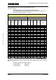
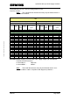
fuse ratings depend on the rated DC link current of each individual
frequency inverter connected to the DC link. The DC link fuses required for
the frequency inverters are specified in Tables 3-1 and 3-2. In this case a
fuse must be provided in both the positive and negative branches of the DC
link.
Copyright © Siemens AG 2005 All rights reserved
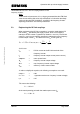
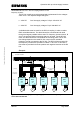
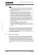
Example:
Line fuses
Line reactors /
DC link fuses
Inverter
M
3 ~
Motor
M
3 ~
M
3 ~
Motor Motor
MM440
22kW
(CT)
MM440
15kW
(CT)
MM420
11kW
Braking resistor
3-ph. 380-480V AC 50/60Hz
PE PE PE
PEPEPE
M
3 ~
M
3 ~
Motor Motor
MM440
1,5kW
MM420
1,5kW
PE PE
PEPE
Line
contactor
L1
L2
L3
PE
2 x 80A 2 x 50A
2 x 40A
2 x 10A 2 x 10A
3 x 80A
3 x 50A 3 x 35A
Cable cross-section
2 x 95mm²
Fig. 3-2: DC link coupling involving 3 supply and 2 additional frequency inverters
connected at the DC link.
A&D SD Page 28/32