
Operating instructions

Operation with up to three supply inverters
MICROMASTER 420 / 440 – DC link coupling between several
Frequency inverters
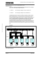
5.3.1 Connecting the DC link coupling at the frequency inverter
The DC link connections are connected at the frequency inverter at
terminals
DC + und DC – . Terminals DC + are connected with DC + and DC – with
DC – of the frequency inverter.
Note:
It is extremely important to ensure that the polarity of the DC link
connections is not interchanged as otherwise the connected frequency
inverters could be destroyed.
5.3.2 Cable cross-sections required and fusing of DC link couplings
When selecting the cable cross-sections required, the DC link coupling
differs in two different areas:
Copyright © Siemens AG 2005 All rights reserved
a. The cross-sections of the cables used to establish the DC link couplings
of the frequency inverter to the associated DC link fuses are
dimensioned corresponding to the DC link fuses of the frequency
inverter. This applies both for the supply inverters as well as for the
frequency inverters coupled through the DC link. For the supply
inverters, this connection must also be implemented and routed so that it
is short-circuit proof.
b. The cross-sections of the cables after the DC link fuses to connect the
drive inverters with one another are dimensioned so that these
correspond to the sum of the rated currents of the line fuses of all supply
inverters multiplied by a factor of 1.2.
Further, the routing type and ambient temperature of the DC link coupling
must be taken into account. As an alternative to using cables to establish
the DC link coupling, after the DC link fuses, a DC busbar, routed in
parallel, can be used. This low-inductance coupling offers the advantage
that the equalization currents between the supply inverters can be reduced
- thus reducing the load on the inverters. Further, using a DC busbar, it is
easier to reduce the cross-section of the DC link coupling. Starting from the
DC busbar, it is possible to branch to the DC link fuses of the frequency
inverter with a short-circuit proof connection with a lower cross-section.
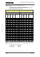
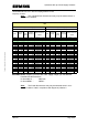
The DC link currents which flow for each frequency inverter (at the rated
operating point) are specified in Tables 3-1 and 3-2.
A&D SD Page 27/32