
Operating instructions
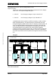

Operation with up to three supply inverters
MICROMASTER 420 / 440 – DC link coupling between several
Frequency inverters
Note:
Under certain circumstances it is no longer guaranteed that the EMC limit
value classes will be able to be fully maintained. It is therefore absolutely
necessary that the EMC Guidelines, specified in the frequency inverter
Operating Instructions are carefully maintained.
5.3 Engineering the DC link couplings
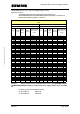
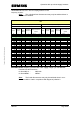
When engineering the DC link connections, it must be noted that the DC
link current I
DC
, provided by the supply inverter, does not correspond
exactly to the line current I
N
(specified in Tables 3-1 and 3-2). The DC link
current I
DC
can be more precisely specified in relationship to the frequency
inverter output current I
A
. The DC link current I
DC
is then given by:
INV
A
MotorADC
V
V
II
η
ϕ
1
cos35.1
max
••••=
Copyright © Siemens AG 2005 All rights reserved
In this case:
I
DC
= DC link current at the DC link terminals of the
frequency inverter
I
A
= frequency inverter output current (motor current)
cosφ
Motor
= motor power factor
V
A
= frequency inverter output voltage
V
max
= max. frequency inverter output voltage
η
INV
= efficiency of the inverter module
In order to simplify the equation, the following assumptions are made:
cosφ
Motor
= 0.86
V
A
/ V
max
= 1 (operation at the max. frequency inverter voltage)
η
INV
= 0.97
This means the following:
ADC II •= 20.1
At the rated operating point with the rated output current I
AN
:
NN ADC II •= 20.1
A&D SD Page 24/32