
Operating instructions

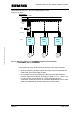
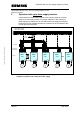

Operation with only one supply frequency inverter
MICROMASTER 420 / 440 – DC link coupling between several
Frequency inverters
A&D SD Page 19/32
Copyright © Siemens AG 2005 All rights reserved
4.8 Operation of the fans in the frequency inverters
In order that the supply inverter is not thermally overloaded, when one of
the connected frequency inverters receives an ON command then the
supply inverter must also receive an ON command. This therefore
guarantees that its fan is operational and the cooling is adequate. If the
supply inverter is powered-up as a result of the internal fan, but the
connected motor may not rotate, then the setpoint can be inhibited in front
of the ramp-function generator for both MICROMASTER420 and
MICROMASTER440 using parameter P1142. This guarantees that the
motor does not rotate even if a setpoint is present.
Exception:
If an option is inserted at the BOP link interface at the supply inverter (e.g.
Profibus module, encoder module, etc.) then for frequency inverter sizes A,
B, and C, the fan is always operational when the line supply voltage is
connected and an ON command to power-up the fan is not necessary.
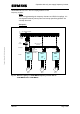
4.9 Risk for the connected frequency inverters in the case of a DC
link short-circuit
When a short-circuit or ground fault occurs in the DC link (in the DC link
coupling or within a frequency inverter), there is a risk that all of the
frequency inverters, connected to the DC link, will be destroyed. This is the
reason that when the drive system is engineered, this aspect should be
carefully taken into account. The number of frequency inverters within a DC
link group should be kept as low as possible.
4.10 Operation on IT line supplies
The frequency inverter without integrated EMC filter can also be used in a
DC link group connected to an IT line supply. In this case the Y capacitor of
the frequency inverter should be removed. A description is provided in the
Operating Instructions of the frequency inverter.