
Operating instructions

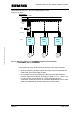
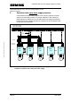

Operation with only one supply frequency inverter
MICROMASTER 420 / 440 – DC link coupling between several
Frequency inverters
A&D SD Page 17/32
Copyright © Siemens AG 2005 All rights reserved
4.3.4 Maximum DC link - cable lengths
The total length of the DC link couplings as a sum, starting from the supply
inverter is 5m.
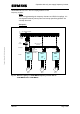
4.4 Braking operation of the DC link group
For the DC link coupling, energy is exchanged between the frequency
inverters through a common DC link. This means that if one or several
frequency inverters is regenerating, then this energy can be provided to the
frequency inverters which are motoring. If the regenerative energy is not
completely drawn by the connected frequency inverters - or not at every
instant in time - then the energy can be dissipated in a connected braking
resistor using the braking chopper that is integrated in the MICROMASTER
440.
In the DC link group, the internal braking chopper may only be activated for
one MICROMASTER 440 frequency inverter. It makes sense if the
MICROMASTER 440 in the DC link with the highest power rating is used for
this purpose. The required braking resistor can be selected in accordance
with the data in Catalog DA51.2.
Note:
o The integrated braking chopper is only active if the frequency inverter
had received an ON command and is actually operational. When the
appropriate frequency inverter is powered-down, then energy cannot be
pulsed in the braking resistor.
o The braking resistors, which are used in the Catalog DA51.2, are
specified for a duty cycle of 5%. The duty cycle can be increased
corresponding by using several braking resistors with a duty cycle of 5%
or other suitable braking resistors. For the DC link coupling, the
regenerative energy could also be supplied from (several) other
inverters. In this case it must be ensured, that the braking power which
is dissipated in continuous operation in the braking resistor does not
exceed the rated power P
INV
N
of the braking inverter. The maximum
short-time braking power P
brake
short
can be calculated with the minimum
possible restistance of the braking resistor R
min
(Table 5-4 of the
MICROMASTER 440 Operating instructions) and the maximum possible
DC link voltage V
DC
max
(
DC 420V at 230V-units resp. DC 840V at 400V-units).
This means the following:
P
brake
short
= V
DC
max
² / R
min
For the DC link coupling the highest permitted value of the duty cycle x
in the Parameter 1237 at MICROMASTER 440 is: x ≤ (P
INV
N
/ P
brake
short
) * 100%