
Operating instructions


Operation with only one supply frequency inverter
MICROMASTER 420 / 440 – DC link coupling between several
Frequency inverters
A&D SD Page 15/32
Copyright © Siemens AG 2005 All rights reserved
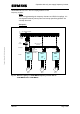
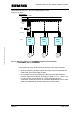
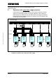
In this particular case, the supply inverter (75kW) is fused, on the line side
with the fuses (200A) specified in the Operating Instructions. The frequency
inverters (11kW and 7.5kW) connected to its DC link must be separately
fused as they cannot be protected by the 200A line fuses of the supply
inverter. The two connected inverters are fused through two phases with
40A (11kW frequency inverter) and 32A (7.5kW frequency inverter)
according to Table 2-2. This means that the DC link coupling must be also
directly fused at the DC link output of the 75kW frequency inverter (with 2x
80A fuses). The reason for this is that this also cannot be protected by the
200A line fuses because of the 25mm² cross-section being used. The
cross-section of the DC link coupling depends on the total rated DC link
currents (I
DCtot
= 54A) of the frequency inverters connected to the supply
inverter. Depending on the cable routing type and the ambient temperature,
a cross-section of, e.g. 25mm² can be used (routing type B1, 2 conductors
conducting current, 40° C ambient temperature). The cable coupling
between the DC link connection of the 75kW frequency inverter up to the
fuses of the DC link coupling should be as short as possible and be
implemented and routed so that it is short-circuit proof. As an alternative to
a short circuit-proof implementation and routing, a cable cross-section can
be used for this coupling which is adequately protected using the 200A line
fuses (depending on the line impedance, the DC link current is
approximately 20% higher than the line current).