
Operating instructions

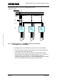
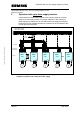

Operation with only one supply frequency inverter
MICROMASTER 420 / 440 – DC link coupling between several
Frequency inverters
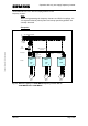
4.3.1 Connecting the DC link coupling at the frequency inverter
The DC link couplings are connected at terminals DC + und DC – of the
frequency inverter. Terminals DC + are connected with DC + and DC – with
DC – of the frequency inverter. If frequency inverters whose rated powers
differ significantly, are coupled with one another, then it should be noted
that the small cable cross-sections of the lower rating frequency inverter
may not be directly connected to the higher rating frequency inverter at the
DC link. In this case, a suitable reduction should be used.
Note:
It is extremely important to ensure that the polarity of the DC link coupling is
not interchanged as otherwise the connected frequency inverters could be
destroyed.
4.3.2 Cable cross-sections required and implementing the DC link
couplings
The cable cross-sections required are obtained from the power rating of the
frequency inverters connected to the supply inverter. The cable cross-
section is selected starting from the supply inverter corresponding to the
sum of the powers connected there and the resulting sum of all of the DC
link currents. The cable cross-section can be lower the greater the distance
to the supply point if the total connected power of the frequency inverters in
the particular section of the line is lower. As an alternative, a DC bus bar,
connected to the supply inverter can be used.
The DC link currents which flow for each frequency inverter (at the rated
operating point) are specified above under Point 2.3. The sum of the DC
link currents of the frequency inverters connected to the supply inverter are
then used to select the cable cross-section of the DC link connection. In
addition, the type of cable routing and ambient temperature must be taken
into account.
Copyright © Siemens AG 2005 All rights reserved
The DC link couplings must be appropriately implemented for the voltages
which occur. The voltage strength required is as follows:
o 450V DC for a line supply voltage of 1/3-ph. 200-240V AC
o 900V DC for a line supply voltage of 3-ph. 380-480V AC
In order to reduce EMC noise, shielded cables must be used for the DC link
coupling. The shield should be connected at both ends through the largest
possible surface area. For frequency inverter sizes A, B and C, the optional
A&D SD Page 12/32