
Operating instructions


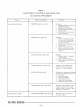


TABLE I.
FUNCTIONS OF CONTROLS AND INDICATORS
ON CENTRAL PROCESSOR
r
Group
Alarm Indicator Lights
Ready Indicator Lights
Control or Indicator
PRIORITY
alarm light (red)
PARITY
alarm light (red)
OVERFLOW alarm light (red)
CARD PUNCH
alarnl light (red)
ECHO
ALARM light (red)
CARD READER
alarm light (red)
CARD PUNCH READY light (green)
Func t
lon
Indicates:
1.
AUTO/MANUAL switch
is
in
NlANUAL position.
2,
Parity alarnl condition.
3.
Central processor does not
have priority.
4.
Card punch or card reader
alarm condition.
Indicates:
1.
Menlory -chec king circuits
of processor detected par-
ity error while processor
in
autonlatic mode.
2.
Parity error connected with
tape reader.
3.
Parl.ty error detected
as
data received from
a
con-
troller through
controller
selector.
Indicates:
1.
Capacity of the A register
was exceeded.
2.
Illegal divide attempted.
3.
Data shifted, leftout of the
A register.
Indicates card punching was
attempted when card punch
was not in
a
ready condition.
Indicates an
uilsuccessful atteixpt
to select
a
controller for ally of
these reasons:
1.
Controller busy
2.
Incorrectaddress
3.
Controller off line
4.
Power off to controller
5.
Malfunctioning controller.
Indicates card reading was
at-
ternpted while the card reader
was not ready (not set up, busy,
misfeed, or card jam.
)
Indicates when card punch
is
In 'ready' status.