
Operating instructions


the index groap that has been selected by the program
(Groups
0
through
3
1).
Each group has four registers,
0
through
3.
When all lights are off, group zero
is
available without special selection. Only index groclp
zero
is
standard on the GE-225 System; additional
groups are optional. Any time a light
is
on in the
index group,
the
o2erator knows that an index grmp
other than zero has been selected.
P
Counter Lights. The fifteen display lights for the
P
counter are located to the right of the INDEX
GROUP indicators. They are n~mbered, left to right,
from
5
through 19, and are arranged in groups of
three to facilitate reading the binary
numl~ers in their
octal representation. By reading these groups, the
oilerator can know the location of the instruction
which appears in the
I
register. The
P
counter
is
useful wnen debugging a program and when checking
for correct operation after a manual branch
comrnand
to a particular program location.
SAVE:
P
Switch. This switch permits the operator
to return to a particular position in theprogram after
he has interrupted it to make a correction, such as to
introduce an instruction manually. The SAVE
P
switch in the downpositionprevents the
P
counter from
incrementing. When the operator returns the SAVE
P
switch to the up (normal) position after manual
operations, the program
is
ready to continue from the
plaze of interruption. When the SAVE
P
switch
is
in
the
dowa position during the automatic mode of oper-
ation, the instruction in the I register is executed
over and over again.
I
Register Lights. The 20 I register display lights
are
lozated below the
INDEX
GRa3P
and
P
counter
lights, and are
number from
0
to 19. They display
the contents of the instruction register. Like the
other register display lights, they are read in their
octal representation. The I register displays the
current instruction,
the instruction that has not yet
been executed or has been only partly executed.
A Register Lights. The 20
A
register display lights
are
located below the
I
register lights. They are
[-qp$[q
ALARM
MANUAL
E
numbered from 0 to 19, and display the contents of
the A register. These are
als~
read in octal. By
using the
XAQ switch (described
later),
the
A
reg-
ister lights can be used to display the contents of
the
Q
register. All data and in;trclctions feed
m2.nually into the central processor go through the
A
register, and are entered by use of the option switches.
Optiojn Switches.
The 20 option switches just below
the
A
register display lights are used to feed infor-
mation into the A register. Each of these toggle
switches enters information into the corresponding
A register position. The numbers
0
through
19
below the
A
register lights may be thought of
as
also applying to the switches. When moved up, the
switches are spring loaded and return automatically
to the center '(normal) position. When moved down,
they
remain in the down position until manually
returned to the norm21 positio2.
W!len the central processor
is
in the manual mode of
operation, moving
an
option switch up causes
a
one
to
be
put into the corresponding position of the
A
register. This
is
indicated
by
an
A
register display
light. Moving an
option switch up has
n9
effect when
the central processor is in the automatic mode of
operation.
Moving an option switch
dow!~ w!len the central proces-
s:lr
is
in the automatic mode causes a one to be put
into the corresponding position of the A register at
the time of a programmed RCS instruction. Specified
switches are left in the
daw~i p~sition while running
certain
rodtines and while generating GAP assem-
blies. These and other special uses of the option
switches are specified in the
program~ner's instrac-
tions to the operator.
RESE'i'
ASwitch. This switch
is
to the left of the
option switches. It is effective only
w!len the central
processor
is
in the mawal made of operation. Like
the option switches, it is spring loaded in the up
pgsition but not in the down position. When moved
either up or
down,
it clears to zero the contents of
the
A
register, and turns off all of the A register
display lights. When the operator
makes a mistake
while using the option switches, he can correct this
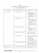
OFF
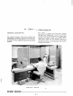
Figure
IV-4.
Control Switches on the Control Console
STOP
ON
PARITY
ALARM