
Operating instructions


engineers, but there are two items of concern
to the operator, the
N
register indicators
and the CLEAR
N
Switch.
N
Register Indicators. These lights are located
in the upper right corner of the maintenance
panel and are labelled
N1,
N2,
N3,
N4,
N5,
and
N6.
TL.ey show the contents of the
N
reg-
ister which
is
a
BCD
character representation
of the input or output for either the paper tape
reader, paper tape punch, or the typewriter.
CLEAR N Switch. This switch
is
to the left
and slightly below the
N
register indicators.
When depressed, it clears the contents of the
N
register to zero. The operator uses this
switch
,
for example, when the typewriter
is
hung in
a
loop and depressing the space bar
does not clear the
N
register. This could hap-
pen
if
someone turns off the typewriter while
a program is running. Depressing the CLEAR
N
switch and manually entering a TON instruc-
tion will cause the typewriter to resume typing.
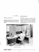
B.
CONTROL CONSOLE. The control console
(Figure IV-3)
is
the most important and most
used panel on the
GE-225.
It
is
sometimes
referred to as having both an indicator panel
and a control panel, for the upper two thirds
of the console contains indicator lights and the
lower third contains control switches. The
indicators are alarm lights, ready lights, and
register display lights for the A, I, and P
registers. The controls are option switches
and control switches.
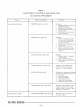
~larm Indicators. The six alarm indicator lights in
the upper left hand corner of the console are danger
signals that
indlcate error conditions have occurred
during system operation, and the program may be
aborted. The cause can be an operator error, a
programming error, or a malfunction in the system
equipment.
All
alarm indicators except the PRIORITY
alarm can be turned off by the RESET ALARM switch.
However, it must be remembered that use of the
RESET ALARM switch can damage the program
if
used when not authorized to do so by the programmer.
The conditions which cause these alarms to come on
are as follows:
PRIORITY Alarm. This alarm
is
turned on
under any of the following conditions:
1.
The
AUTO/MANUAL
switch
is
in the
MANUAL position.
2.
The STOP ON PARITY ALARM switch
is
engaged and a parity error
is
detected.
3. The central processor does not have
priority (access to memory).
4,
A
card punch or card reader alarm
condition has occurred.
PARITY Alarm. If the STOP ON PARITY ALARM
switch
is
engaged when a parity error
is
detec-
ted, the centralprocessor will halt. The PARITY
alarm can be turned off by pressing the RESET
ALARM switch or by programmed instructions.
The
PARITY alarm is turned on under any of
the following conditions:
1.
The memory-checking circuits of the
central processor detect aparity error
while the
AUTO/MANUAL
switch
is
in
the AUTO position.
2.
The parity checking circuits associated
with the paper tape reader detect a
parity error.
3.
A
parity error
is
detected
as
infor-
mation
is
received frdm a controller
through the controller selector.
OVERFLOW Alarm. The central processor does
not halt
on an overflow alarm. The alarm may
be reset automatically several times during
a
normal MPY instruction. The indicator also
can be turned off by depressing the RESET
ALARM switch or by programmed instructions.
The OVERFLOW alarm
is
turned on under any
of the following conditions
:
1.
The capacity of the
A
register isexce-
eded during arithmetic operations.
2.
An illegal divide
is
attempted.
3.
H
one bit
is
shifted out of bit position
one of the
A
register during a shift-
left operation.
CARD
PUNCH
Alarm. This alarm
is
turned on
any time a WCB, WCD, or
WCF
instruction
is
attempted when the cardpunch
is
not in the ready
condition. As already noted, the PRIORITY
alarm also comes on, and the centralprocessor
halts. The alarm can be reset only by pressing
the RESET ALARM switch.
ECHO Alarm. This alarm
is
turnedonwhen the
central processor makes an unsuccessful
at-