
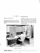
Operating instructions


The second rack contains the majority of the elec-
tronic counters, registers, timing circuits, and control
logic associated with the processor.
The third rack contains the remaining registers, the
magnetic core memory and its associated timing and
control logic, and the logic for the controller selector.
Cable Connections
All peripherals are connected to the central proces-
sor by cables. The typewriter
is
connected directly
by cable to the first rack of the central processor.
The card reader
is
also connected to the first rack,
but through a junction box mounted in the rear of the
console desk.
The peripheral equipments which have controllers
are connected to the controller selector by cables so
that each peripheral controller
is
connected in paral-
lel with the controller selector and in series with
every other controller. Cables are connected to two
plugs in the third rack of the central processor.
The
output cable from the central processor
is
connected
to one plug, and leads to the input plug of the
first
controller. Controllers are connected to each other
by cables which lead from the output of one to the
HASR
5
)S68
DC
381
CHO
70
4
DS7
input of the next. The output of the last controller
leads back to the controller selector, and connects
to the second of the two plugs in the third rack of
the central
processor.
The card punch
is
connected to the central processor
through a plug located on the same connector panel
on the third rack as the two plugs for the controller
selector. The punch cable
is
clamped in place by
means of a 'shoe' connector attached to the end of
the cable.
Controls and Indicators
The
GE-225
System operator constantly watches and
uses the controls and indicators of the central proces-
sor. Most of the control switches and indicator
-
lights are on the control console which provides
switches for manual control, indicates the status of
equipment, and displays the contents of certain reg-
isters. In ,addition to the control console, there
is
a
maintenance panel which has three areas of interest
and
use to the operator.
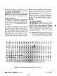
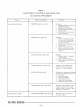
A.
MAINTENANCE
PANEL.
The maintenance panel
of the central processor, illustrated in Figure
IV-2,
is
located inside the door which
is
above
the control console. It
is
usedmostly
by
service
CLE
1534
DC
Figure IV-2. The Maintenance Panel of the Central Processor