
Instruction manual

56
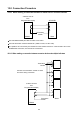
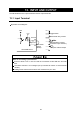
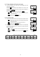
14-1-4 Excitation voltage check mode
6. Press the 1↵ key to check the excitation voltage supplied to the
sensor from the AD-4532B. In the example display shown to the
right, the excitation voltage is 5 V 5 .
Press the 1↵ key to go to the DAV voltage check mode dav.
1> Moves to the next check mode without performing the
current check mode
ESC Returns to the CHeCk display.
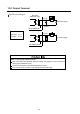
14-1-5 DAV voltage check mode
7. The DAV voltage check mode checks the D/A output voltage.
1> Moves to the next check mode without performing the
current check mode
1↵ Displays the DAV output voltage.
ESC Returns to the CHeCk display.
8. Connect a digital multimeter. Use the following keys to check the
output voltage.
1∧ Increases the DAV output value by one.
1∨ Decreases the DAV output value by one.
1↵ Finishes the DAV voltage check mode and enters the
zero calibration mV/V value check mode Cal 0.
ESC Cancels the operation and returns to the dav display.
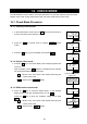
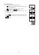
14-1-6 Zero calibration mV/V value check mode
9. The zero calibration mV/V value check mode displays the mV/V
value at zero calibration.
Press the 1↵ key to check the zero calibration mV/V value. In the
example display shown to the right, the value at zero calibration is
0.14234 mV/V 0.14234.
Press the 1↵ key to go to the span calibration mV/V value check
mode 5pan.
1> Moves to the next check mode without performing the
current check mode
ESC Returns to the CHeCk display.
volt
5
CHeCk volt
dav
0
CHeCk dav
7
CHeCk dav
-4
CHeCk dav
Cal 0
0.14234
CHeCk Cal 0
To go to step 10