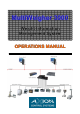
MultiWeigher 3000 00 0 MultiWeigher 3 Weight Information Management System OPERATIONS MANUAL
LICENSE The MultiWeigher 3000 software is licensed to the end user to be installed on one computer per individual license. The MultiWeigher software license comes supplied with a single USB License Key that must be fitted to the computer running the MultiWeigher 3000 software.
PRODUCT DISCLAIMER The purchase, installation and use of products manufactured or distributed by AxionCS are deemed to be at the Customer's consent to the following conditions: 1. The Customer acknowledges that any advice provided by AxionCS in respect of the use or installation of the Products is given in good faith and the Customer acknowledges that it is solely responsible for deciding whether the Products are appropriate to their proposed installation, situation and intended use. 2.
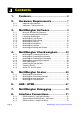
Contents 1. Features...................................................... 6 2. Hardware Requirements ....................... 7 2.1.1. 2.1.2. 3. 3.1.1. 3.1.2. 3.1.3. 3.1.4. 3.1.5. 3.1.6. 3.1.7. 3.1.8. 3.1.9. 4. 4.1.1. 4.1.2. 4.1.3. 4.1.4. 4.1.5. 4.1.6. 4.1.7. 4.1.8. 5. 5.1.1. 5.1.2. 5.1.3. 5.1.4. Hardware Requirements ........................................................... 7 Hardware - Typical Overview .................................................... 8 MultiWeigher Software ................
8.1.4. 8.1.5. 8.1.6. 8.1.7. 8.1.8. 8.1.9. RS232 Interface – Yamato CE2100 ........................................ 54 RS232 Interface – Anritsu SF and SV ..................................... 55 Serial Interface Communication Modes .................................. 56 Ethernet Device Server - Hardware ........................................ 57 Ethernet Device Server - Software .......................................... 58 RFID Hardware .....................................................................
1. Features MultiWeigher 3000 is designed to run on a Microsoft Windows operating system. The MultiWeigher 3000 software is designed to meet the growing requirements for real-time weight capture, data collation and analysis. MultiWeigher 3000 provides framework and structure for a factory-wide Weight Information Management System (WIMS). The MultiWeigher software is capable of monitoring, checking and grading the weight data of various products that are passed over the connected scales or checkweighers.
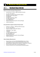
2. Hardware Requirements 2.1.1. Hardware Requirements Minimum Computer Hardware Requirements • • • • • • • • • • Intel Pentium® 2.2GHz or AMD equivalent Processor 17” TFT Colour Monitor 50 MB Free (minimum install) Hard Drive Space 256 MB Scratch "Temp" space 512 MB RAM 512 MB Virtual Memory Space 32+ MB Graphics Card 10/100 MB Ethernet Multiple USB ports (One port for Security Dongle) CD/DVD ROM Drive Recommended Computer Hardware Requirements • • • • • • • • • • Pentium IV 3.
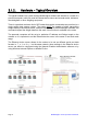
2.1.2. Hardware - Typical Overview The typical hardware in a system that the MultiWeigher software will interface to, consist of a personal computer, multi-port serial to Ethernet device server and several scales, indicators, checkweighers or other weighing equipment. There is a practical maximum limit of 255 scales that can be connected at any one time in a single weight data capture system.
3. MultiWeigher Software 3.1.1. Microsoft Windows Environment As with most MS Windows software programs the insertion of data is predominantly carried out by clicking the data field with use of a mouse or mouse pad, and to a lesser extent by using the keyboard. When the data bases are entered such as operators, products, etc… minor entry of information is carried out via the keyboard. Accessing the relevant areas of the program is undertaken by clicking on the relative folder or tabs.
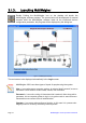
3.1.3. Launching MultiWeigher Double Clicking the MultiWeigher icon on the desktop will launch the MultiWeigher software package. The screen below will be displayed for several seconds while the MultiWeigher software loads all the connected devices configuration parameter, this progress will be displayed by the sliding bar. Figure 1 - MultiWeigher Launching The next screen to be displayed automatically is the Login screen. MultiWeigher 3000 uses three types of inputs for people using the system.
3.1.4. MultiWeigher Login Screen MultiWeigher 3000 data capture software identifies three user levels and their passwords for authentication and protection. Level 1 Operator user name only gains access to the top layer folders; products, checkweighers, scales and reports, the lower layer folders will not be visible. Level 2 Administrator user name has access to the same folders as the operator plus the lower layer folders passwords and backup/restore.
When a user level and password are entered correctly the MultiWeigher 3000 software will automatically search for a PC connected USB Hasp security device. The USB Hasp will identify the version of software purchased and will also either allow the software to run in Demonstration Mode “USB Hasp security device NOT INSTALLED” or Registered Mode “USB Hasp security device INSTALLED”.
3.1.5. MultiWeigher Device Setup To setup MultiWeigher 3000 the Technician level and password will need to be activated as this level will gains full access to all the MultiWeigher 3000 folders. The first task is to install and configure all connected devices; this is done by using the Devices folder on the lower layer. The devices folder stores all the details for each piece of weighing equipment connected in the field; such as weight scales or checkweighers.
Save > when first opening the device folder this button will be grayed out. The Save button will only become active after the Accept button has been pressed, this confirms that the changes made to this device need to be stored and saved. Zoom > the zoom button allows the user to view and filter All, Used and Unused devices stored in the system First Record > the First record button when pressed will display all the details for the first device installed; this is also referred to as ID Number 1.
• • • MT 8434 Mettler Toledo mini tiger retail scales SIMSCALES Scales Simulator SIMCHECKWEIGHER Checkweighers Simulator • Comms Mode The comms mode is a drop down selection box Available communication methods are RS232, RS485 and TCP/IP. e.g.
• Error Interval The Error Interval field is the fastest weighment speed practical by an Operator. This value is stored in milliseconds and if weights are received in a shorter time period the weighment is recorded as an error. e.g. the operator puts a product on the scale and pressing print several times.
3.1.6. MultiWeigher Settings The MultiWeigher 3000 settings folder stores all the system hardware and software configuration settings and should only be modified by authorized and experienced personnel. [Configuration > Settings > General] Figure 5 - General Settings Screen • Use Virtual Thread allows the user to either select the standard communications thread or a virtual communication thread; tick selects, blank unselects.
Restart Data Capture enables the MultiWeigher to start capturing data Stop Data Capture enables the MultiWeigher to stop capturing data [Configuration > Settings > Scales] Figure 6 - Scale Settings Screen • Update time to Data Capture is the time period for MultiWeigher to update the weighing scales data capture folder. Time is editable from 5 to 3,600 seconds • Scale Auto Log Off Time is the minimum time period for a scale to perform a complete weighment cycle.
[Configuration > Settings > Checkweighers] Figure 7 - Checkweighers Settings Screen • Checkweigher Database Poll Time sets the time interval to which the MultiWeigher software updates its graph database with the Target, Average and Standard Deviation values that are present in the Checkweigher folder at that point in time. This creates important plant production trending.
[Configuration > Settings > AQS / UTML] Figure 8 - AQS / UTML Settings Screen • Enable Assistance Tool for Regulations Compliance enables the use of the AQS tools during the scale and checkweigher simulations when the Enable box is checked Page 20 MultiWeigher 3000 Operations Manual
3.1.7. MultiWeigher Passwords The MultiWeigher 3000 Password folder is only accessible by the Level 2 Administration and Level 3 Technician user names; the Level 1 Operator user name does not have access to this folder, so it will not be displayed. The password folder allows the user to Create, Modify and Delete operators and their associated passwords plus the ability to set the level for the user’s password.
• Add RFID Code to User allows the administrator to allocate RFID key fobs or RFID wristbands to a user that will be using the weighing equipment in the factory. The RFID code is 128Bit encrypted for security purposes and cannot be reproduced to another key fob or wristband. • View/Edit User List allows the administrator to easily view the registered system user and their specific user details. It also gives the administrator the ability to edit the registered user’s details.
3.1.8. MultiWeigher Products MultiWeigher 3000 software can store a total of 250 products in its database. To add a new product to the MultiWeigher database, select the Products folder on the top layer of the screen, then press the Insert button and fill in the required data fields. Figure 11 - Product Screen Insert > clicking on the Insert button will clear the product folder and allows the user to enter a new product information and its characteristic details.
Save > when first opening the device folder this button will be grayed out. The Save button will only become active after the Accept button has been pressed, this confirms that the changes made to this product need to be stored and saved. Search > the search button allows the user to view all products stored in the database, and the ability to then select a product for modification or deletion.
• Product Pouch Size (mm) This field is to store the pouch size of a product • Product Line Number • Tolerances This field is to store the line number of a product There are four fields to enter target weight tolerances; they are LoLo, Lo, Hi, and HiHi These values are checked as weight value is not equal to set weight target Characters = 4 Numeric Update CW Codes updates the Company Product Name and Description into the Checkweigher data and vice versa Import Products enables user to import product info
Right-click on the Product window enables users to transfer the Product information into a selected Checkweigher This function can also be used to recall the product code to be run by the Checkweigher Send Product Code information and additional setpoints to the selected Checkweigher.
3.1.9. MultiWeigher Backup and Restore At the end of a Week, Month or Year the active databases can be archived and stored for future analysis; these created user files are known as Archived Database. The archived database can be saved in any directory under any permissible windows file name on the MultiWeigher hard drive, backup drive or connected network server drive.
Press the start button, MultiWeigher will then open the standard Microsoft Window “Save As”. From this window the user can select a previous file name and location or type in a new archived file name and file location. e.g. 19-08-2008 CW Database.gbk Restore database procedure Only restore the database if the MultiWeigher software is updated to a newer version and the previously backed up database need to be restored in the newer version software.
4. MultiWeigher Checkweighers 4.1.1. MultiWeigher Checkweigher Screen To view the live real-time data being captured from the connected checkweighers click on the top layer Checkweigher folder; this will then open the low layer checkweigher folders as can be seen in the example image below. If the data capture has been activated in the [Configuration > Login] screen or the Device folder, the Comms Status field will display either [ Comms Good! ] or [ Comms Failure! ].
• Product Code and Name These fields store the checkweigher Product Code and Name being captured by the MultiWeigher These fields are writable by the user • Total Weight and Units These fields store the total weight and its unit of the checkweigher product being captured These fields are NOT writable by the user • Line Number This field stores the production Line Number of the checkweigher being captured This field is NOT writable by the user • Batch No.
Average This field store the overall Average weight of the captured checkweigher product This field is NOT writable by the use Average Over Last __ Minute / Samples stores the Average weight over a period of time or over a number of samples.
• Write Mode Enabled Changing or writing new data to the checkweigher controller is done simply by placing a tick (√) in the Write Mode Enable box (□); this will then switch the software from Data Capture mode in to Data Edit mode. • Write When the user has adjusted/changed the required data fields, the user will need to click on the Write button; this instructs the software to re-send all the information on the screen to the A&D Dolphin checkweigher controller.
Figure 17 – Checkweigher Line Trend Graph • Histogram Pressing the Histogram button will open the Trend Histogram page.
4.1.2. MultiWeigher Checkweigher Simulator To create a Checkweigher Simulator, select the SIMCHECKWEIGHER driver in the Devices setting. When the simulator device is enabled, a checkweigher simulator is created as shown in the screen below. Figure 18 - Checkweigher Simulator Screen Before starting to run the Checkweigher Simulator, it needs to be set up.
4.1.3. MultiWeigher Checkweigher Dashboard To view certain data being captured from the multiple enabled checkweighers click on the Checkweigher Dashboard folder at the top layer of MultiWeigher window. This will then open the low layer Checkweigher Dashboard screen as shown in the example image below. To Print the Summary of CW Dashboard Figure 19 - Checkweigher Dashboard Screen Right-click on the Checkweigher Dashboard screen opens up the Area Properties window as shown.
4.1.4. MultiWeigher Checkweigher Reports The MultiWeigher 3000 software package offers user friendly configurable, viewable and printable reports. Reports can be obtained for both Checkweighers and Weight Scales; the data is retrievable from the real-time weight capture database and the time polled logging databases. To obtain detailed and meaningful reports the user must first set-up the reports field table; this will decide the type of information the reports are to display or print.
The sample report below has been generated from a single checkweigher. The data in the report was printed after two separate short product production runs. Figure 22 - Checkweigher Report The checkweigher report summary can also be displayed as a color line graph. In the example below the red Target weight was 500g, the green Average weight was 496.1g and the brown Standard deviation was 15.5.
4.1.5. A&D 4404 Dolphin The MultiWeigher 3000 software can be set to automatically or manually poll the A&D 4404 checkweigher controller, the frequency at which the polling operates is stored in the settings folder.
4.1.7. Yamato CE2100 The MultiWeigher 3000 software can be set to automatically or manually poll the Yamato CE2100 controllers, the frequency at which the polling operates is stored in the settings folder.
5. MultiWeigher Scales 5.1.1. MultiWeigher Scale Screen The MultiWeigher 3000 software can be set to automatically or manually poll the connected weight scales, the frequency at which the polling operates is stored in the settings folder. The following are the data fields and their character lengths that are received from the A&D EW scales.
• Prod Code The Product Code is the code number stored in the checkweigher controller, this number is a unique number typically from 01 to 99 designed to verify what product is being check weighed. • Time The Time field is the exact time the last weighment had been received for this particular scale device, the weights are transmitted from the scale by the operator pressing the print button.
5.1.2. MultiWeigher Scale Global Settings Changing user data fields during the scale data capture operation is possible in MultiWeigher 3000, the software allows for the fields of Operator, Batch Code and Product to be changed, this function is activated by right mouse clicking on the specific data filed requiring the change.
5.1.3. MultiWeigher Scale Simulator To create a Scale Simulator, select the SIMSCALE driver in the Devices setting. When the simulator device is enabled, a scale simulator is created in table as shown in the screen below. The example below shows three scale simulators that run simultaneously. Figure 24 - Scale Simulator Screen Check in the Operator by checking on the Status OUT box; the status changes to IN and the scale simulation for the checked in operator will start automatically.
5.1.4. MultiWeigher Scale Reports Selecting the top layer Reports tab and the lower layer tab Scales the user can produce custom reports for all the packing scales in the factory. The weighing data that has been captured from these scales is stored in the Active database as seen below (Figure 11) Figure 25 – Scale Report Screen • Filter Button > is used to custom drill down in to the data for specific reports.
• Export button > will open the standard Microsoft Window “Save As” from here the user can navigate to any directory to save the exported file, the file can be save as a (DAT) Data file, (TXT) text file or an (RTF) Rich Text File. These file types can be opened by various other software packages like Microsoft Excel or Linux Open Office Calc.
• Printed Report > Clicking on the Printed Report allows the user to view the report of the information captured from the enabled scale Figure 28 - Scale Report Page 46 MultiWeigher 3000 Operations Manual
6. AQS / UTML From 1 July 2010, manufacturers and packers will be able to apply the Average Quantity System (AQS) as their measurement systems. To know more about the AQS system, please visit: http://www.measurement.gov.au/TradeMeasurement/Business/Pages/AverageQuantitySy stem.
The first half on the left hand side of the AQS screen shows the 3 rules that need to be fulfilled to comply with the AQS. The other half on the right hand side of the screen shows the 2 rules that need to be fulfilled to comply with the UTML.
• T2 Counts T2 Counts is the total number of products that need to be rejected to meet the T2 Error rule • Reject Weights Reject Weights is the total weights that have been rejected to comply with the T2 Error requirement ¾ UTML Average Compliancy • Target Weight The Target Weight is the weight to be achieved by the products in a production run • Nominal Weight The Nominal Weight is the weight marked on the end-user / customer package of the monitored product.
7. MultiWeigher Debugging MultiWeigher makes available to experienced technicians a live on screen debugging terminal interface, from this debug screen all the serial traffic flow can be viewed and therefore diagnosed for errors and correct interfacing. The technician will enable the data view and select a specific device that needs to be monitored, the communications ports can be stopped and restarted and the data view window can be cleared at any time.
8. Interface Connections 8.1.1. RS232 Interface – A&D 4404 Dolphin The RS-232C is used to connect to either an Ethernet Hub or Personal Computer. When installing a serial option only one option can be installed at any one time.
8.1.2. Serial Interface RS485/RS422 – A&D 4404 The RS-422/485 interface can use commands to control the indicator. The interface can read weighing data or parameters or store parameters to the indicator. The interface can connect a maximum of 32 units and a personal computer. The unit can be specified by an address appended to the command. RS-485 can use 2-wire or 4-wire.
8.1.3.
8.1.4. RS232 Interface – Yamato CE2100 Specifications Communication Method Transmission Method Transmission Standard Transmission Distance Transmission Rate Transmission Character Code Start Bit Data Bits Parity Stop Bits Half duplex Bit serial Asynchronous, start/stop RS232C 15m (Max.) 1200, 2400, 4800, 9500 bps ASCII 1 bit 7 bits, 8 bits None, Even, Odd 1 bit, 2 bits Data may not be transmitted from the computer if CTS and RTS of the computer are not connected.
8.1.5.
8.1.6. Serial Interface Communication Modes A&D AD4404 Indicator Stream Mode The data is output on each display update. If the data cannot be output completely due to a slow baud rate, the data is output at the next update. Auto Print Mode The data is automatically printed on batch finish. Manual Print Mode When the preset print key is pressed or the assigned terminal is connected, the data is output.
8.1.7.
8.1.8. Ethernet Device Server - Software The Serial to Ethernet device servers can normally be configured and setup by various software methods, these can include Telnet, Console, Web browser and Manger software. The manager software can be set to automatically search for an Ethernet connected device server thus making easier to locate if the IP address is not known.
The examples in Figures 21 and 22 show the Sena and Moxa WEB browser interface using Microsoft Internet Explorer. When the device server IP address is entered into the WEB browsers address bar you will be prompted to enter and User Name and Password.
8.1.9. RFID Hardware Radio frequency identification (RFID) is an automatic identification method, relying on storing and retrieving data using devices called RFID tags or transponders.
Specifications General Software Version Software Development Operating Systems MultiWeigher 3000 Ver 1.
9. Index 2 wires ................................................40 4 wires ................................................40 Administration Screen......................10 Auto print mode ..................................41 Baud rate ......................................36, 40 Checkweighers .............................22 Command mode .................................41 Comms Failure ...................................22 Comms Good ......................................22 Config Screen ..................
10. Figures Figure 1 - MultiWeigher Launching .................................................................................... 10 Figure 2 - Login Screen ..................................................................................................... 11 Figure 3 - Log on Validation ............................................................................................... 12 Figure 4 - Device Screen ................................................................................................
NOTES
MultiWeigher 3000 Operations Manual Page 65