
Instruction manual


5
3. CONNECTION
3.1. Setting the AD-4212C and the AD-8923-CC
Set the following items so that the AD-4212C and the AD-8923-CC have the
same value for each item.
Item AD-4212C AD-8923-CC
Baud rate 600, 1200, 2400*, 4800, 9600, 19200 bps
Data bits, parity 7 bits EVEN*
Stop bits 1 bit*
Terminator <CR><LF>*
Data format A&D standard format −
Communication control No RTS/CTS control −
Data output mode Stream mode −
* Factory setting for the AD-8923-CC. The factory setting for the AD-4212C
is the same unless otherwise specified.
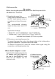
3.2. Connecting the cables
Connect the cables using the connectors located on the rear of the AD-8923-CC.
Connection example to the AD-4212C and a PLC
Note
Be sure to ground the AD-4212C and the AD-8923-CC.
PLC
(CC-Link master station)
A
D-8923-CC
RS-232C connector (D-Sub 9-pin)
Connect to the power supply
Refer to “3.3. Turning the power on”.
RS-232C cable
provided with the D-4212C
CC-Link connector (5-pin)
G
round
CC-Link network
C
C-Link network
To other remote stations
such as the AD-8923-CC.
AD-4212C
Ground