AD-8923-CC Remote Controller (CC-Link) INSTRUCTION MANUAL 1WMPD4002124
© 2010 A&D Company, Limited. All rights reserved. No part of this publication may be reproduced, transmitted, transcribed, or translated into any language in any form by any means without the written permission of A&D Company, Limited. The contents of this manual and the specifications of the instrument covered by this manual are subject to change for improvement without notice. .
CONTENTS 1. INTRODUCTION ...........................................................................................................2 1.1. Features ..................................................................................................................2 2. DESCRIPTION OF EACH PART ..................................................................................3 2.1. Display ....................................................................................................................4 2.2.
1. INTRODUCTION This manual describes how the AD-8923-CC remote controller works and how to get the most out of it in terms of performance. Read this manual thoroughly before using the AD-8923-CC and keep it at hand for future reference. 1.1. Features Connecting the AD-8923-CC remote controller and the AD-4212C series production weighing unit will enable transmission of the weight data to a PLC using CC-Link. z Displays the weight data transmitted from the AD-4212C.
2. DESCRIPTION OF EACH PART Display AC adapter input jack DC input terminal CC-Link connector Keys Accessories FG terminal CC-Link plug 1 pc. RS-232C connector (D-Sub 9-pin) See the note below. Rear View Connector operation lever 1 pc. Note AC adapter 1 pc. When the AD-8923-CC is to be built into a weighing system, be sure to ground the FG terminal. Please confirm that the AC adapter type is correct for your local voltage and receptacle type.
2.1. Display REMOTE CONTROLLER AD-8923 Turns on while the AD-4212C is in the standby mode. RESPONSE STABLE FAST MID. CAL SAMPLE PRINT MODE RE-ZERO SLOW Weighing speed indicators STABLE indicator ON:OFF Unit indicator z Displays the weight data received. When the unit is “g” (gram), the unit indicator turns on. z When the weight value is stable (the header of the weight data received is “ST”), the STABLE indicator turns on.
3. CONNECTION 3.1. Setting the AD-4212C and the AD-8923-CC Set the following items so that the AD-4212C and the AD-8923-CC have the same value for each item. Item AD-4212C AD-8923-CC Baud rate 600, 1200, 2400*, 4800, 9600, 19200 bps Data bits, parity 7 bits EVEN* Stop bits 1 bit* Terminator * Data format A&D standard format − Communication control No RTS/CTS control − Data output mode Stream mode − * Factory setting for the AD-8923-CC.
Connection example to the CC-Link network (weighing instruments No.1 through No.4) Connect a terminating resistor only to the stations at each end of the network. CC-Link master station (Ground) Weighing instrument AD-8923-CC AD-8923-CC AD-8923-CC AD-8923-CC AD-4212C AD-4212C AD-4212C AD-4212C No.3 No.4 No.1 No.2 z The value of the terminating resistor varies depending on the CC-Link cable used. z Use the same resistor at each end of the network.
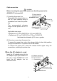
When the external 24-VDC power supply is used Connect an external 24-VDC power supply to the DC input terminal located on the rear of the AD-8923-CC. Precautions on using the external power supply CAUTION z Use a power supply within the rated voltage range (24 VDC±10%). Never use a power supply with a voltage exceeding the rated range. • It may cause damage or heat buildup. • The AD-8923-CC may not function properly. z Ground the FG terminal of the switching power supply used.
Cable connection CAUTION Before inserting the power line, make sure that the power to the AD-8923-CC is turned off. DC input terminal (1) Inserting the power line Press down the release button on the DC input terminal using a screwdriver and insert the power line. The recommended stripping length for the power line is 10 mm. AD-8923-CC rear Power line Release button Screwdriver Applicable wire range • Single wire: φ1.0 mm (AWG 26) to φ1.2 mm (AWG 16) • Twisted wire: 0.3 mm2 (AWG 22) to 0.
3.4. Operation z Displays the data transmitted by the weighing instrument connected. z The AD-8923-CC key functions when connected to a weighing instrument are listed below: (e.g. when the AD-4212C is connected) Model Keys of the AD-8923-CC ON:OFF CAL Switches between the weighing AD-4212C mode and the standby mode. Enters the calibration mode using a weight. SAMPLE Switches the minimum display. PRINT MODE RE-ZERO Used for the function setting mode and calibration mode.
Calibration procedure Calibrates the AD-4212C using the calibration weight. Operation 1. Warm up the AD-4212C for 30 minutes or more with nothing on the pan. 2. Press the CAL key. Cal 0 is displayed. z If you want to cancel calibration, press the CAL key. The display will return to the weighing mode. z If you want to change the calibration mass value, press the SAMPLE key. Press the RE-ZERO key to select the mass value, and press the PRINT key to store it. Cal 0 is displayed. RESPONSE STABLE FAST MID.
4. FUNCTION SETTING Function setting specifies the AD-8923-CC performance. The parameters are stored in non-volatile memory, and are maintained even if the power line or AC adapter is removed. The function setting menu consists of two layers. The first layer is the “Class” and the second layer is the “Item”. Each item stores a parameter. Press the SAMPLE key to select an item and press the RE-ZERO key to change the parameter. Then, press the PRINT key to store the new parameter.
4.1. Display and keys The STABLE indicator turns on to indicate that the parameter displayed is in effect. Selects a class or item. Changes the parameter. When a class is displayed, moves to an item in the class. When an item is displayed, stores the new parameter and displays the next class. When an item is displayed, cancels the new parameter and displays the next class. When a class is displayed, exits the function setting mode and returns to the weighing mode. 4.2.
4.3. Initializing the AD-8923-CC Initialization restores the function settings of the AD-8923-CC to factory settings. Operation 1 Turn the power on. - - - - - or weighing mode display appears. 2 While holding down the ON:OFF key, press the PRINT key. Clr is displayed. 3 Press the PRINT key. To cancel this operation, press the CAL key 4 Press the RE-ZERO key to select “go”. 5 Press the PRINT key to perform initialization. After initialization, - - - - - or weighing mode display appears. .
5. RS-232C CONNECTOR The RS-232C cable provided with the AD-4212C can be connected directly. 5.1.
6. CC-Link CONNECTOR The AD-8923-CC CC-Link is a remote device station of CC-Link ver.1.10. When a CC-Link is used, the AD-8923-CC can be controlled by the PLC remote I/O or remote registers. So, the program can be simple. And connection to a PLC is simple, thus, a weighing system can be built easily. The setting values of CC-Link are changed in the function setting CCl. 6.1. CC-Link interface specifications Station number 1 to 64 Baud rate 156 kbps, 625 kbps, 2.
Memory map Remote register (Number of occupied stations: 1) Blank “Name” column: internally reserved (not used).
Remote I/O (Number of occupied stations: 1) Blank “Name” column: internally reserved (not used).
Numeric values of the remote register All the values are hexadecimal. Negative values are expressed by the two’s complement. Decimal Hexadecimal (32 bits) -10 FFFFFFF6 -1 FFFFFFFF 0 00000000 1 00000001 10 0000000A Weight value examples 1.000 will be 1000, thus expressed as 0x000003E8. (RWr0001: 0x0000, RWr0000: 0x03E8) -1.000 will be -1000, thus expressed as 0xFFFFFC18.
Decimal point RX0008 to RX000A, 3-bit binary notation RX000A RX0009 RX0008 Decimal point position 0 0 0 No decimal point 0 0 1 First digit 0 1 0 Second digit 0 1 1 Third digit 1 0 0 Fourth digit 1 0 1 Fifth digit Decimal point position example When displaying 1.000, express 3 as a decimal point at the third digit, thus 0x011. (RX000A: 0, RX0009: 1, RX0008: 1) Re-zero / Tare Sets the weighing instrument to zero. When the remote I/O register turns on (1), re-zeroing is performed.
6.2. Timing chart Below examples are when the station number is set to 1. When connecting to a power supply When the AD-8923-CC is connected to a power supply and the CC-Link is ready, the request flag of initialization (RX0018) becomes active. The master station confirms that RX0018 is active, performs initialization and turns the reply flag of initialization (RY0018) ON. The AD-8923-CC turns the request flag of initialization (RX0018) OFF and turns the remote READY flag (RX001B) ON.
Requesting initialization from the master station When requesting the initial data setting to the AD-8923-CC from the master station, turn the request flag of initial data setting (RY0019) ON while the remote READY flag (RX001B) is active. The AD-8923-CC turns the remote READY flag (RX001B) OFF and performs initial data settings. When initial data settings are complete, the reply flag of initial data setting (RX0019) is turned ON.
6.3. Fixing the decimal point position Using the function setting of dpp, the decimal point position of the value displayed on the AD-8923-CC and the decimal point position of the weight value output via CC-Link can be fixed. In this way, even if the minimum display is switched using the SAMPLE key, the digit position for CC-Link output does not change.
7. TROUBLESHOOTING Symptom eerror 10 appears. (Bar display) remains and the weight value is not displayed. ------ Description Communication settings of the AD-8923-CC do not match with those of the weighing instrument. Check the settings such as baud rate and parity and correct them as necessary. For details, refer to “3.1. Setting the AD-4212C and the AD-8923-CC”.
8. SPECIFICATIONS Power supply : External 24-VDC power supply (24 VDC±10% / 700mA) or AC adapter (Output: 12 VDC / 300mA) Please confirm that the AC adapter type is correct for your local voltage and receptacle type. Transmission system : RS-232C, CC-Link (CC-Link ver.1.10 remote device station) Communications connector : D-Sub 9-pin (male) (RS-232C connector to the weighing instrument) 5-pin (male) (CC-Link connector) External dimensions : 144 (W) X 110 (D) X 72 (H) mm Mass : Approx. 1.
3-23-14 Higashi-Ikebukuro, Toshima-ku, Tokyo 170-0013 JAPAN Telephone: [81] (3) 5391-6132 Fax: [81] (3) 5391-6148 A&D ENGINEERING, INC. 1756 Automation Parkway, San Jose, California 95131 U.S.A.